
Proximity Alarm

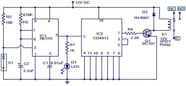
The circuit described utilizes three inverters (U1a, U1b, and U1c) configured in a manner that forms an RC oscillator. The oscillation frequency is contingent upon the resistance (R1) and capacitance values (C1 and C2) selected, as well as the inherent characteristics of the inverter IC. The oscillation generates a square wave output, which is then processed by a voltage coupling stage consisting of capacitors C3, C4, and diode D2. This stage rectifies the oscillating signal, producing a positive DC voltage.
The output of the voltage coupling circuit feeds into the input of the third inverter (U1c). In its low state, U1c ensures that transistor Q1 remains off, preventing the activation of the piezo buzzer (BZ1) and thereby silencing any sound output. The sensitivity of the circuit can be adjusted by tuning the values of capacitors C1 and C2. When these capacitors are set to their most sensitive point, the circuit can detect a hand placed within a range of 3 to 5 inches, triggering an alert when this threshold is crossed.
To initiate the circuit, it is recommended to set C1 and C2 to approximately half of their maximum capacitance values and then apply power. Upon powering the circuit, it should begin oscillating, allowing for the detection mechanism to function as intended. This design exemplifies a straightforward yet effective approach to creating a proximity sensor with audible alert capabilities.Inverters U1a and U1b are connected in a simple RC oscillator circuit. The frequency is determined by the values of R1, C1 C2 and the internal characteristics of the integrated circuit. As long as the circuit is oscillating, a positive dc voltage is developed at the output of the voltage-couple circuit: C3, D2 and C4.
The dc voltage is applied to the input of U1c-the third inverter amplifier-keeping its output in a low state, which keeps Q1 turned off so that no sound is produced by BZ1. With C1 and C2 adjusted to the most sensitive point, the pickup plate will detect a hand 3 to 5-inches away and sound an alert. Set C1 and C2 to approximately one-half of their maximum value and apply power to the circuit. The circuit should oscillate and 🔗 External reference
Related Circuits
This circuit is designed to detect whether the load of a battery charger or plug-in adapter is properly connected. The load may consist of a set of batteries needing charging or any other device that operates on low DC...

This is a simple water level alarm circuit made using a 555 timer IC. The circuit will produce an alarm when the water level reaches a preset level. The water level alarm circuit utilizing a 555 timer IC is designed...
This weblog discusses electronic circuit schematics, PCB design, DIY kits, and electronic project diagrams. The circuit diagram presented is for a magnetic proximity switch, which has numerous applications across various fields. The circuit utilizes a magnetic reed switch (S1)...
This circuit can be constructed using readily available low-cost components, some of which may be found in a junkbox. The specified value of 22 ohms for resistor R1 results in an average current of approximately 65 mA through the...
This is a simple but effective alarm circuit that can reset itself after a user-defined time. It features normally open and normally closed triggers, enhancing its practicality. The circuit utilizes a 555 timer, allowing the alarm to automatically reset...
This is a simple proximity switch utilizing the IC 4049. The IC 4049 is a bipolar monolithic integrated circuit designed for metal detection systems and proximity sensing applications. It includes an oscillator formed by an external parallel resonant tank...