
Successive approximation a-d converter

The described A/D converter circuit is designed to achieve high-speed conversion of bipolar signals into a digital format with a resolution of 14 bits. The two AM25L03 components operate in tandem to implement the successive approximation technique, which iteratively narrows down the input signal's digital representation. This method is known for its efficiency in achieving high accuracy with relatively low power consumption.
The comparator's two-stage architecture enhances performance by allowing the HA2605 front-end amplifier to effectively manage the input signal's characteristics before it reaches the decision-making stage of the conversion process. This arrangement is critical for addressing settling time challenges, which can adversely affect the accuracy and speed of the conversion. By reducing the settling time at the summing node, the circuit ensures that the input signal stabilizes quickly, allowing for more rapid successive approximations and thereby increasing the overall throughput of the A/D converter.
Offset nulling is a crucial calibration step for the HA2605 amplifier, as it ensures that any inherent voltage offsets do not introduce errors into the conversion process. This adjustment is vital for maintaining the integrity of the signal being processed, particularly in high-precision applications where even minute discrepancies can lead to significant deviations in the output data.
Overall, this A/D converter design exemplifies a sophisticated approach to high-speed analog-to-digital conversion, leveraging advanced components and careful circuit design to optimize performance and accuracy.A bipolar input, high speed A/D converter uses two AM25L03s to form a 14-bit successive approximation register. The comparator is a two-stage circuit with an HA2605 front-end amplifier used to reduce settling time problems at the summing node
Careful offset-nulling of this amplifier is needed.
Related Circuits
This circuit converts a sine wave into a square wave. It consists of a single 2-input NAND Schmitt trigger configured as an inverter, with a trigger level adjustment at its input. As the input voltage exceeds the gate's trigger...
The circuit is a temperature-to-pulse-width converter. The LM3524 is used to convert the output of an LM135 temperature transducer into a pulse width that can be measured by a digital system, such as a microprocessor-controlled data acquisition system. In...
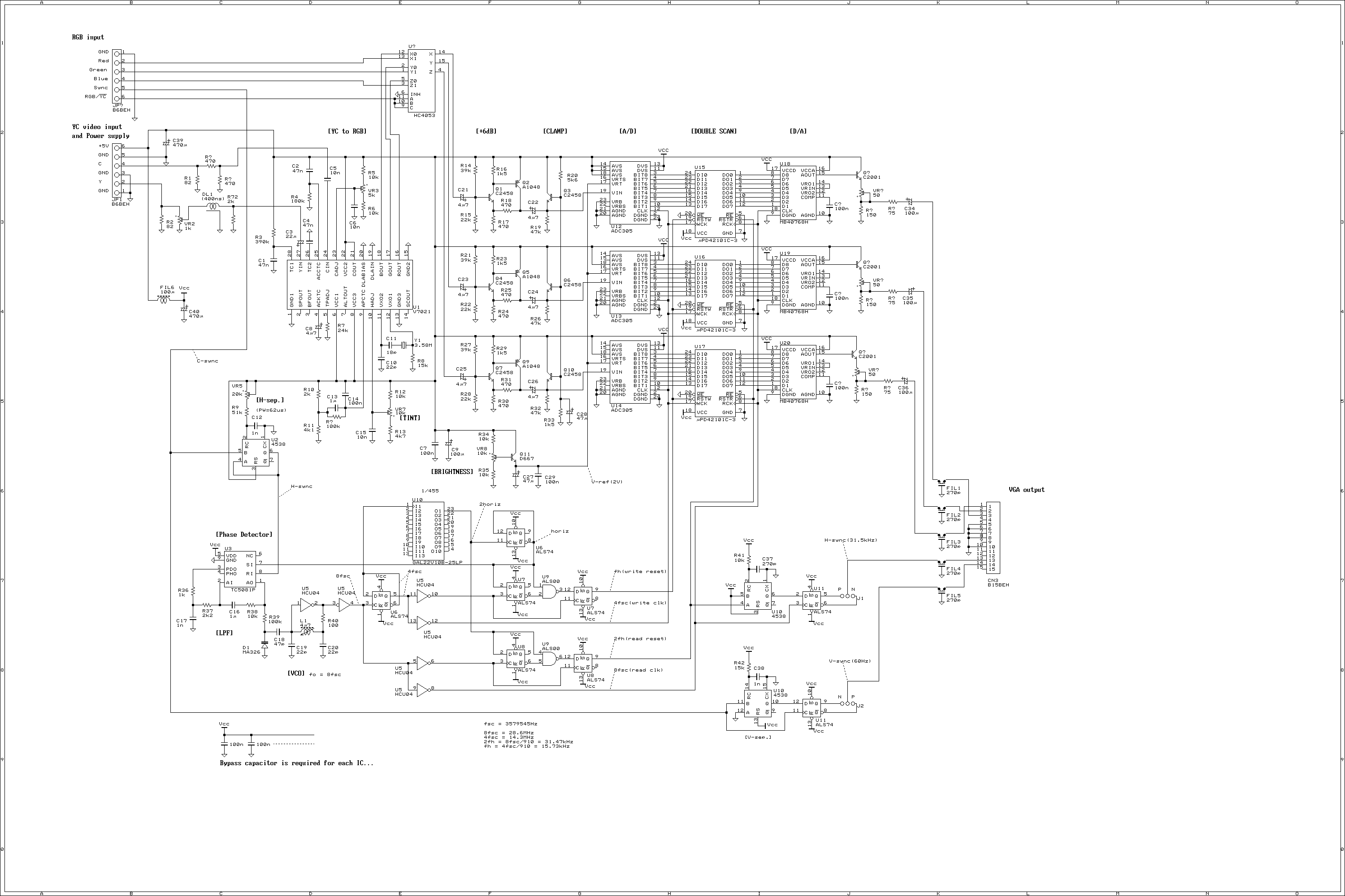
This is a video scan converter to display NTSC video signal into VGA monitor. Normally, the VGA monitor occupies most desk top space, so that everybody will be thinking that if the VGA monitor can be used for video...
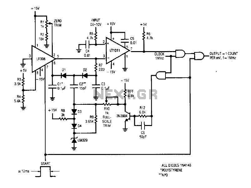
The simple 4-digit converter circuit has an output count of 1, designed for a frequency range from f-IMHz to 10.000 MHz. All diodes used in the circuit are IN4146 "POLYSTYRENE" NPO. The circuit utilizes the LF398 at the input...
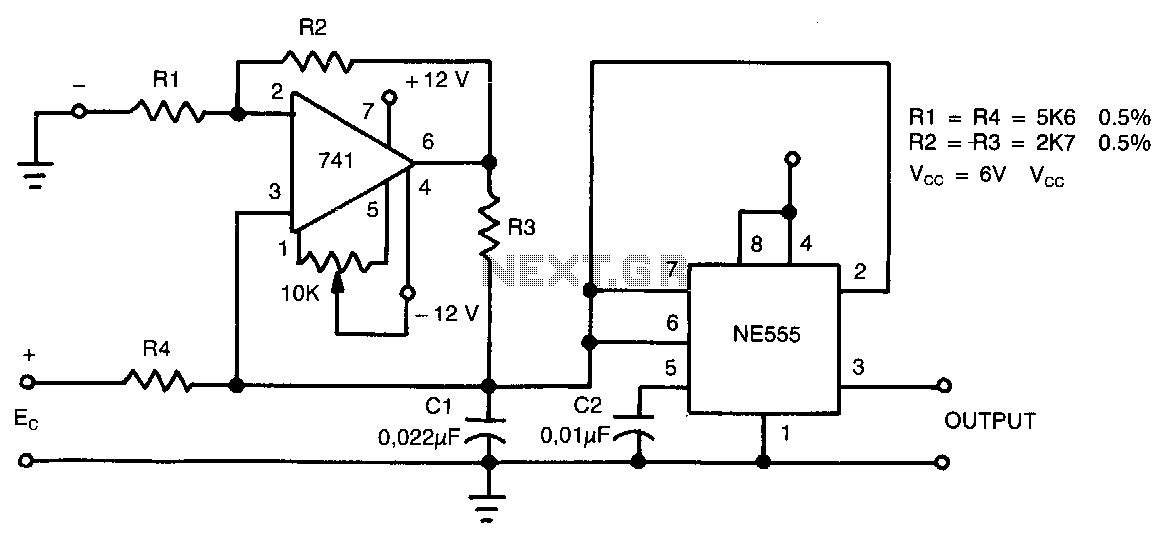
This circuit can accept positive, negative, or differential control voltages. The output frequency is zero when the control voltage is zero. The 741 operational amplifier forms a current source controlled by the voltage Ec to charge the timing capacitor...
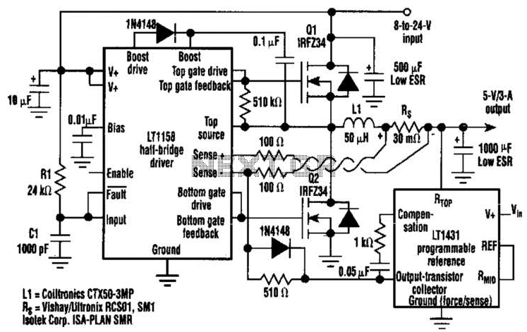
This regulator achieves 90% efficiency with a 12-V input and a 5-V output. It utilizes the LT1158 and LT1431 components from Linear Technology, Inc. High efficiency is accomplished by synchronously switching two power MOSFETs in a step-down switching regulator....