
Wave Joule Thief circuit

LED chaser circuits are designed to create visually appealing light patterns by sequentially illuminating a series of LEDs. These circuits can be implemented using various technologies, including discrete components, logic ICs, or microcontrollers, each offering unique advantages and complexity levels. Discrete transistor circuits are often simpler and can be built with minimal components, while logic IC-based designs provide more precision and control over timing and sequencing. Microcontroller-based chaser circuits allow for greater flexibility, enabling the programmer to customize light patterns and timings extensively.
Despite their popularity, a significant limitation of many LED chaser circuits is their reliance on higher voltage levels than what a single AA alkaline battery can provide. Standard LEDs require a forward voltage of approximately 2.2V, and certain colors, such as blue and white, require even more, typically around 3.2V. This voltage requirement poses a challenge for battery-powered applications, as a single AA battery typically outputs only 1.5V.
The Joule Thief circuit is a practical solution to this problem. It is a simple, efficient boost converter that can step up the voltage from a single alkaline battery to a level sufficient to power LEDs. The circuit typically consists of a few components, including a transistor, a resistor, an inductor, and a diode. The Joule Thief operates by rapidly switching the transistor on and off, which causes the inductor to store energy and then release it at a higher voltage. This allows the circuit to effectively light LEDs that would otherwise be unlit due to insufficient voltage from the battery.
In summary, LED chaser circuits offer a captivating visual display but often face voltage limitations when powered by a single AA battery. The Joule Thief circuit provides an effective means of overcoming this challenge, allowing for the operation of various LED types in a compact and power-efficient manner.A bunch of LEDs neatly turning on and off on a precise timing lights running one way, then the other way Its relaxing, soothing, and hypnotic. There are so many LED chaser/scanner/sequencer circuits out there, some are made with discreet transistors, some based on logic ICs, and more and more others are using microcontrollers. There is one thing in common with all of the LED chaser circuits you find on the net none of them can operate with just one alkaline battery!
Most of us know that LEDs need at least 2.2V or so to light. Blue and white LEDs require even higher, typically 3.2V. So obviously you cant use just one AA battery to operate an LED chaser. But we all know that there is Joule Thief that boosts voltage high enough to light any LEDs. 🔗 External reference
Related Circuits
Building battery boxes for the Speedster. Although this topic may not seem thrilling, builders converting vehicles to electric drive often discover that the process of making a car run on battery power is relatively straightforward. However, about 50% of...
To initiate the process, the LOAD switch and Reset switch must be pressed simultaneously within 24 seconds; otherwise, the countdown will commence from 99. A pulse input can be connected to a 555 astable multivibrator, but it must be...
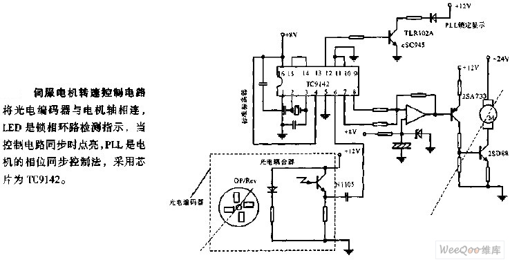
The servo motor speed control circuit connects the photoelectric encoder to the motor shaft. The LED serves as an indicator light for the phase-locked loop (PLL) detection, illuminating when the control circuit is synchronized. The PLL employs a phase...
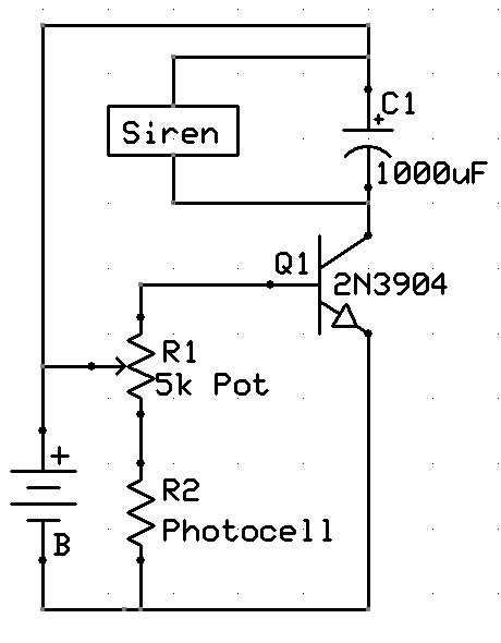
A new user has recently discovered a Laser Alarm System and has decided to explore this project. The Laser Alarm System is a security device that utilizes laser beams to detect unauthorized entry or movement within a designated area. The...
This circuit is designed to control the mains voltage by switching it on and off at intervals ranging from just under a second to up to 10 minutes. It is particularly useful for testing mains-operated equipment over extended periods...

This circuit must be used between the drive voltage of such a transformer and track. On JP1, the transformer is connected to JP2, the rails are connected to JP3, is a TTL "High" position when there is a tax...