
Amplifier Timer Circuit Schematic

The circuit operates on the principle of signal detection and timing, utilizing an audio input to control a relay that manages power to connected devices. The initial stage involves the amplification and squaring of the audio signal through operational amplifiers IC2A and IC2B, which enhances the signal to a level suitable for monitoring. LED D4 serves as a visual indicator of the audio signal's presence, illuminating briefly when the signal is detected.
The timing function is managed by IC3, which is configured to count the absence of the audio signal. Capacitor C3 plays a crucial role in resetting this timing mechanism. When the audio signal is present, C3 is charged, preventing IC3 from reaching its threshold. However, if the audio signal is absent for the specified duration, IC3 triggers a change in its output state at pin 2, transitioning from low to high. This transition turns off the transistors Q1 and Q2, which are responsible for driving the relay. The relay's deactivation results in the disconnection of power to SK1, effectively shutting down the connected devices.
The circuit includes provisions for immediate manual control through switch P2, allowing for the quick deactivation of the system regardless of the audio signal state. Additionally, the reset mechanism provided by C5 and R9 ensures that IC3 is properly initialized upon power-up, establishing a reliable starting condition for the timing operation. This design is particularly useful in applications requiring automatic power management based on audio signal presence, ensuring energy efficiency and equipment protection.This circuit turns-off an amplifier or any other device when a low level audio signal fed to its input is absent for 15 minutes at least. Pushing P1 the device is switched-on feeding any appliance connected to SK1. Input audio signal is boosted and squared by IC2A & IC2B and monitored by LED D4. When D4 illuminates, albeit for a very short peak, I C3 is reset and restarts its counting. Pin 2 of IC3 remains in the low state, the two transistors are on and the relay operates. When, after a 15 minutes delay, no signal appeared at the input, IC3 ends its counting and pin 2 goes high. Q1 & Q2 stop conducting and the relay switches-off. The device is thus completely off as also are the appliances connected to SK1. C5 & R9 reset IC3 at power-on. P2 allows switch-off at any moment. 🔗 External reference
Related Circuits
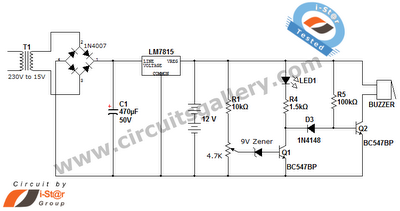
This is a straightforward 12V rechargeable smart battery charger circuit. It can be utilized as a charger for car batteries, inverter batteries, emergency light batteries, and more. An automatic indicator alarm circuit accompanies this battery charger schematic. The primary...
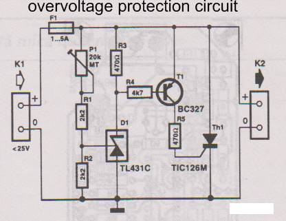
This overvoltage protection or crowbar protection circuit is used where protection against high voltage surges is necessary. The circuit consists of several components. This overvoltage protection circuit, commonly referred to as a crowbar circuit, serves as a critical safety mechanism...
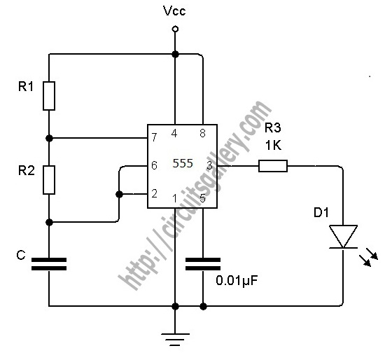
The astable multivibrator is an oscillator circuit that generates continuous pulses without requiring any external triggering. The oscillation frequency and time period can be manually adjusted by modifying the values of resistors R1, R2, and capacitor C1. A 555...
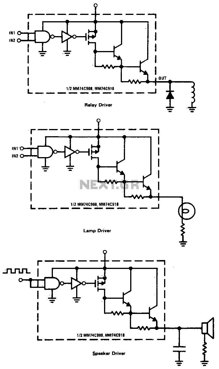
CMOS drivers for relays, lamps, speakers, and similar applications provide extremely low standby power consumption. When operating at Vcc = 15 V, the power dissipation per package is typically 750 nW when the outputs are not drawing current. Consequently,...
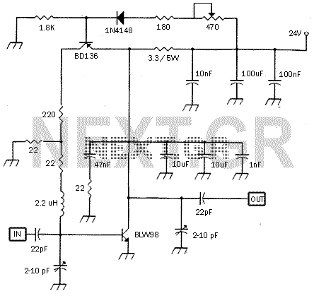
This small circuit is a linear amplifier for driving small UHF TV transmitters. Its gain is 7 dB and can amplify a signal between 450-800 MHz. You can drive the circuit with 1 to 1.5 Watts signal. Better use...
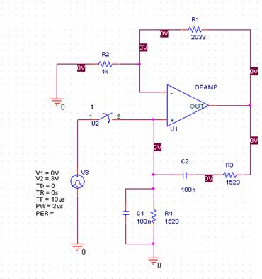
In this laboratory experiment, the objective is to design the frequency-determining network for a 1 kHz sinusoidal oscillator. The specified values are as follows: Capacitance = 100 nF and Resistance = 1520 ohms. The output voltage waveform of the...