
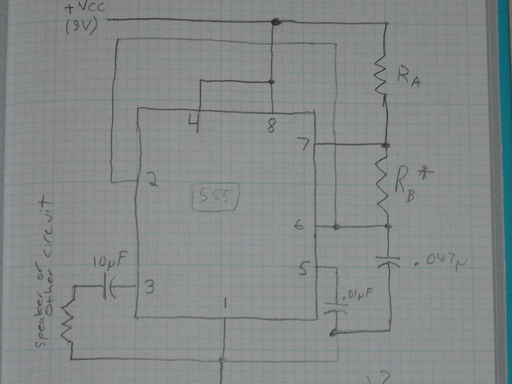
Square Wave Generator (For Resonant Air-Gap Transformer)
The chosen project involves developing a safer and more efficient electronic device, replacing the homemade x-ray machine that posed significant health risks. The new project could focus on a variety of alternatives, such as a low-power medical imaging device using non-ionizing radiation methods, or a diagnostic tool that utilizes advanced sensors and microcontrollers for enhanced functionality.
For instance, a potential design could incorporate a digital imaging system utilizing infrared or ultrasound technology. This system would consist of a microcontroller unit (MCU) that processes signals from sensors and converts them into visual representations. The schematic may include components such as a power supply circuit, signal conditioning circuits, an analog-to-digital converter (ADC), and a display interface for real-time imaging.
The power supply circuit would ensure that the device operates within safe voltage and current limits, while the signal conditioning circuits would amplify and filter the signals from the sensors before they reach the ADC. The ADC would convert the analog signals into digital format for processing by the MCU, which could be programmed to analyze the data and provide feedback through a user interface, possibly using an LCD screen or a computer connection.
In summary, the new project aims to create a modern, safe, and efficient electronic device that surpasses the previous homemade x-ray machine in terms of safety and functionality, utilizing advanced technology to improve medical diagnostics.I`ve decided on a project for the new year that is ~~less likely to lead to sterilization~~ better than my old project (which was a homebrew x-ray mac.. 🔗 External reference
Related Circuits
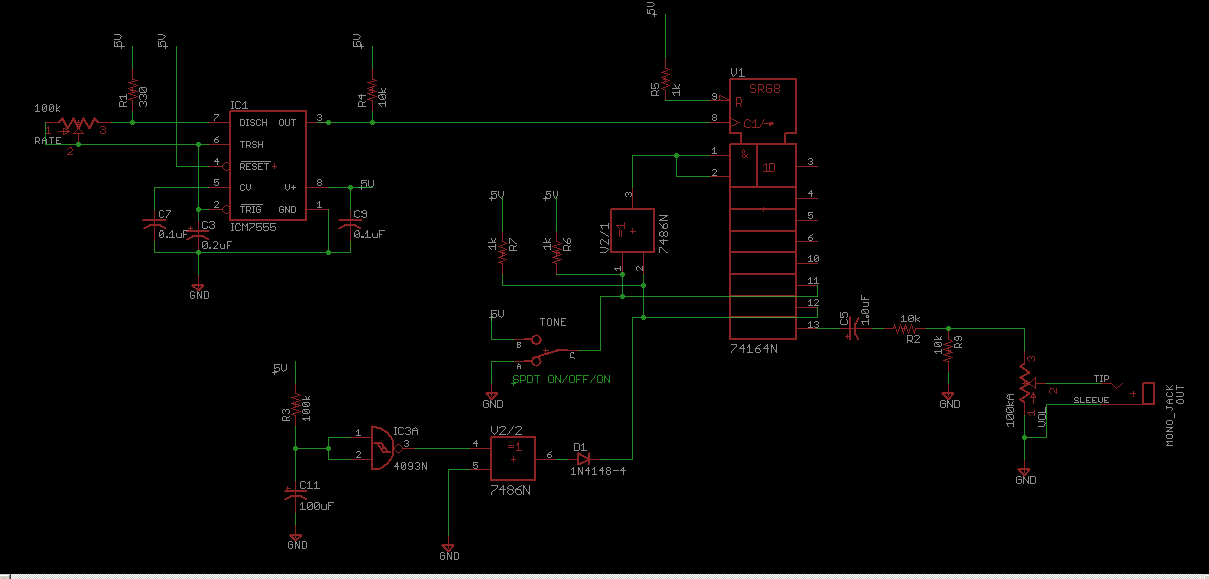
Schematic for the CMOS Linear Feedback Shift Register Vintage Atari Sound Effects Generator circuit. The circuit design consists of a CMOS Linear Feedback Shift Register (LFSR) that is utilized to generate sound effects reminiscent of vintage Atari games. The LFSR...
This circuit generates sine wave oscillations, but it can also be modified to produce triangle or square wave functions. The frequency is adjustable by varying the current. By disconnecting the 20k resistor (RIN) from the reference (REF) pin (pin...
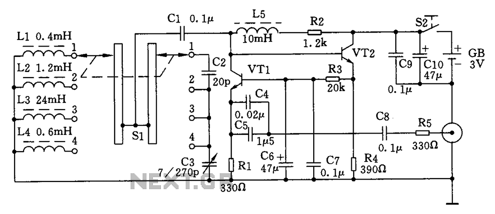
This is a simple high-frequency signal generator. By changing the inductance of the LC resonant circuit using the band switch S1, the high-frequency oscillation frequency range can be altered. The generator is divided into four frequency stages: the first...

This circuit generates a pure sine wave with a total harmonic distortion (THD) of -80 dB and a frequency equal to the cutoff frequency (fc) of the filter in IC3. It utilizes a counter, an 8-channel analog multiplexer, and...
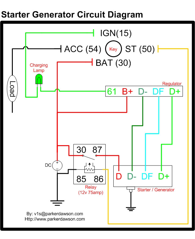
Circuit diagrams for both a Bosch and a Delco-Remy Starter-Generator are available, noting that the circuits differ. Due to a computer crash, the original diagrams and the associated email address were lost. However, in May 2004, both the email...

Utilize the Maxim MAX292 switched-capacitor filter integrated circuit to convert a square wave into a sine wave. The operational frequency range of the circuit spans from 5.2282 Hz to 8928.6 Hz when the microcontroller is functioning at a 16-MHz...