
Pure Sine-Wave Generator Circuit

The described circuit is a sophisticated waveform generator capable of producing high-fidelity sine waves with minimal distortion. The integration of a TTL counter allows for precise digital control over the frequency generation process, while the 8-channel analog multiplexer facilitates the selection of different signal paths, enhancing versatility in signal routing.
The fourth-order low-pass filter, constructed from two cascaded Sallen-Key topologies, effectively attenuates unwanted high-frequency components, ensuring that the output sine wave maintains its integrity. The choice of Sallen-Key filters is advantageous due to their simplicity and effectiveness in achieving a flat passband response alongside a sharp roll-off beyond the cutoff frequency.
The cutoff frequency selection mechanism, which utilizes digital inputs to define the frequency range, provides a high level of customization. By connecting the D0 through D6 inputs to either -5 V or ground, the user can select from 128 discrete frequency steps, allowing for precise tuning of the output frequency. This feature is particularly beneficial in applications requiring specific frequency outputs.
The inclusion of a 100 kΩ potentiometer for output level adjustment adds another layer of functionality, enabling the user to fine-tune the amplitude of the generated sine wave. The range of adjustment, from Vw - 1.5 V to Vss + 1.5 V, allows for compatibility with various signal processing stages that may follow the output of this circuit.
Overall, this circuit design represents a robust solution for generating high-quality sine waves, suitable for a variety of applications in signal processing, testing, and other electronic systems requiring precise waveform generation. A TTL counter, an 8-channel analog multiplexer, and a fourth-order low-pass filter can generate 10- to 25-kHz sine waves with a THD better than -80 dB. The circuit cascades the two second-order, continuous-time Sallen-Key filters within ICS to implement the fourth-order low-pass filter.
To operate the circuit, choose the filter`s cutoff frequency,^, by tying IC3`s D0 through D6 inputs to-5 V or ground. The cutoff frequency can be at 128 possible levels between 1 and 25 kHz, depending on those seven digital input levels.Because the circuit ties D0 through D{, to ground Jc equals 1 kHz.
The 100-kQ potentiometer adjusts the output level between Vw - 1.5 V and Vss + 1.5 V.
Related Circuits
This circuit functions with inaudible (ultrasonic) sound. Sound of frequency up to 20 kHz is audible to human beings. The sound of frequency above 20 kHz is called ultrasonic sound. The circuit described generates (transmits) ultrasonic sound of frequency...
The LM1036 is a DC-controlled circuit designed for tone (bass/treble), volume, and balance adjustments in stereo applications, including car radios, televisions, and audio systems. It features an additional control input for easy loudness compensation. The circuit includes four control...
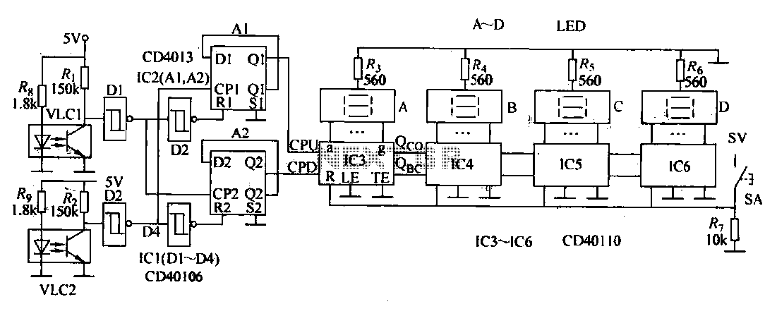
This document describes an electronic winding machine with manual, electric, and semi-automatic features. The specific example highlighted includes an electronic counting function that assists users in managing motor windings. The circuit design consists of various components as illustrated in...
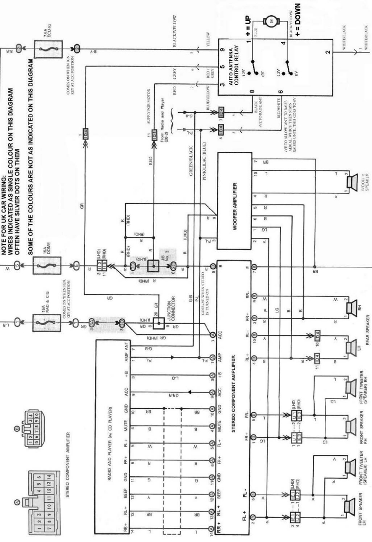
The following circuit illustrates an electrical circuit diagram for the MR2 MKII electric aerial. Features include control by an Aerial Control Relay, which consists of... The MR2 MKII electric aerial circuit is designed to facilitate the automatic operation of the...
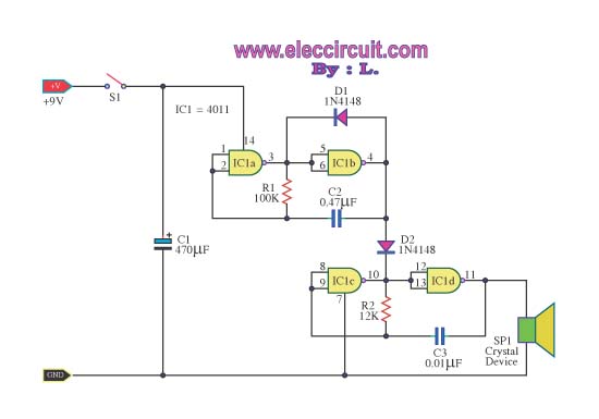
This resonance generator circuit, also known as an oscillating sound generator, is designed using the CMOS integrated circuit 4011 (Quad 2-Input NAND Gate). It consists of four NAND gates. Each oscillator circuit utilizes two gates. The circuit is capable...
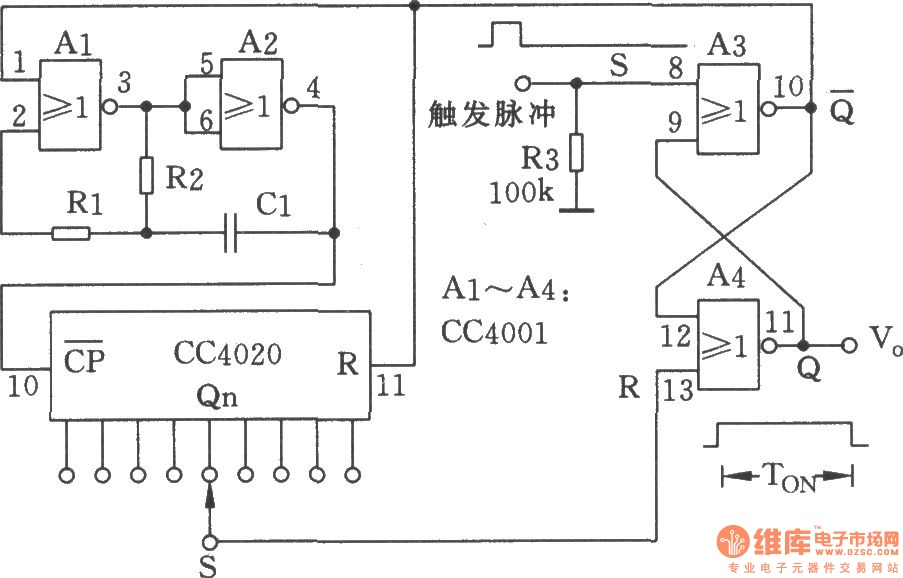
The NC monostable multivibrator circuit depicted in the chart consists of four 2-input NOR gates (CC4001) and a 14-bit binary serial counter/divider (CC4020). It is primarily utilized as a time delay switch or timer in automatic control equipment. The NC...