
Ultrasonic switch circuit

The ultrasonic sound circuit operates in the frequency range of 40 kHz to 50 kHz, utilizing a 555 timer configured in astable mode to generate the necessary signal. This circuit is designed as a remote control system composed of a transmitter and a receiver. The transmitter employs an ultrasonic transducer to effectively emit ultrasonic sound waves, powered by a 9V PP3 battery.
The receiver circuit includes an ultrasonic receiver transducer, which detects the emitted ultrasonic sound. Upon detection, the receiver transducer converts the ultrasonic waves back into electrical signals. These signals are subsequently amplified by a two-stage transistor amplifier, typically consisting of transistors T3 and T4. Following amplification, the signals are rectified and filtered to produce a stable DC voltage.
This DC voltage is then fed to an operational amplifier (op-amp), specifically IC2, in inverting mode. The inverting input of IC2 receives the filtered DC voltage, while the non-inverting input is connected to a variable DC voltage through a preset resistor (VR2). This configuration allows for the adjustment of the threshold level at which the relay (RL1) is activated.
When the ultrasonic sound is sufficiently detected, the output of the op-amp switches low, turning on transistor T5. This, in turn, provides base bias to transistor T6, which activates the relay. The relay can control various electrical or electronic devices, allowing for versatile applications of the circuit.
For optimal performance, the frequency of the ultrasonic sound can be fine-tuned using another variable resistor (VR1). It is crucial to maintain proper alignment between the transmitter and receiver, as ultrasonic waves are highly directional. Additionally, the receiver can be powered using a battery eliminator for continuous operation.
In applications requiring a latch function, a DPDT relay can be integrated into the circuit, enabling the load to be switched on and off. For timed operations, a 555 timer can be configured in monostable mode at the output of IC2, allowing for a delay in relay activation based on the timing components chosen.
It is important to note that due to the nature of ultrasonic waves, the circuit may experience false triggering from external ultrasonic sources, particularly when additional components like flip-flops are used. Careful consideration of the operating environment is advisable to mitigate this issue.This circuit functions with inaudible (ultrasonic) sound. Sound of frequency up to 20 kHz is audible to human beings. The sound of frequency above 20 kHz is called ultrasonic sound. The circuit described generates (transmits) ultrasonic sound of frequency between 40 and 50 kHz. As with any other remote control system this cirucit too comprises a mini transmitter and a receiver circuit. Transmitter generates ultrasonic sound and the receiver senses ultrasonic sound from the transmitter and switches on a relay.
The ultrasonic transmitter uses a 555 based astable multivibrator. It oscillates at a frequency of 40-50 kHz. An ultrasonic transmitter transducer is used here to transmit ultrasonic sound very effectively. The transmitter is powered from a 9-volt PP3 single cell. The ultrasonic receiver circuit uses an ultrasonic receiver transducer to sense ultrasonic signals. It also uses a two-stage amplifier, a rectifier stage, and an operational amplifier in inverting mode. Output of op-amp is connected to a relay through a complimentary relay driver stage. A 9-volt battery eliminator can be used for receiver circuit, if required. When switch S1 of transmitter is pressed, it generates ultrasonic sound. The sound is received by ultrasonic receiver transducer. It converts it to electrical variations of the same frequency. These signals are amplified by transistors T3 and T4. The amplified signals are then rectified and filtered. The filtered DC voltage is given to inverting pin of op-amp IC2. The non- inverting pin of IC2 is connected to a variable DC voltage via preset VR2 which determines the threshold value of ultrasonic signal received by receiver for operation of relay RL1.
The inverted output of IC2 is used to bias transistor T5. When transistor T5 conducts, it supplies base bias to transistor T6. When transistor T6 conducts, it actuates the relay. The relay can be used to control any electrical or electronic equipment. Important hints: 1. Frequency of ultrasonic sound generated can be varied from 40 to 50 kHz range by adjusting VR1. Adjust it for maximum performance. 2. Ultrasonic sounds are highly directional. So when you are operating the switch the ultrasonic transmitter transducer of transmitter should be placed towards ultrasonic receiver transducer of receiver circuit for proper functioning. 3. Use a 9-volt PP3 battery for transmitter. The receiver can be powered from a battery eliminator and is always kept in switched on position. 4. For latch facility use a DPDT relay if you want to switch on and switch off the load. A flip-flop can be inserted between IC2 and relay. If you want only an ON-time delay use a 555 only at output of IC2. The relay will be energised for the required period determined by the timing components of 555 monostable multivibrator.
5. Ultrasonic waves are emitted by many natural sources. Therefore, sometimes, the circuit might get falsely triggered, espically when a flip-flop is used with the circuit, and there is no remedy for that. 🔗 External reference
Related Circuits
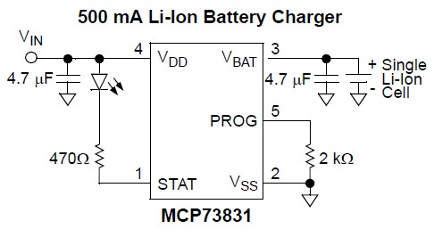
Nokia BL-4C and BL-5C are 3.7V, 700-1000mAh (various) lithium-ion batteries that have three terminals. These terminals include a positive terminal, a ground, and a BSI (Battery Status Indicator) terminal, which presents a fixed resistance value that needs to be...
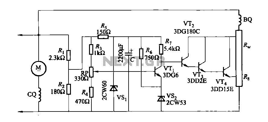
The DC generator automatic voltage regulator circuit is illustrated in Figure 7-53. This circuit is designed for a 40kW, 230V DC shunt complex machine, with a voltage change rate of up to 2.5 percent. In Figure 7-53, BQ represents...
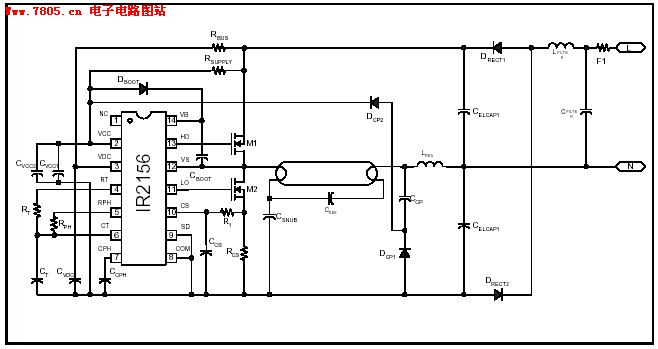
The IR2156 provides a cost-effective solution for fluorescent electronic ballasts. It integrates features such as lighting tube error protection and a programmable working frequency, which includes warm-up, lighting, and continuous operation of the ballast. The IR2156 is a highly integrated...
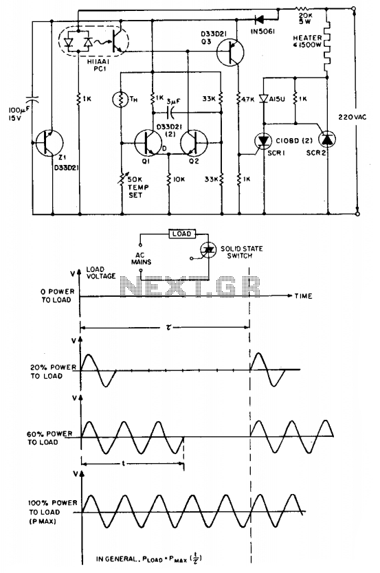
The "zero voltage switching" technique is commonly utilized to modulate heating and similar types of AC loads, where the time constant associated with the load (ranging from tens of seconds to minutes) is sufficiently long to allow smooth proportional...
The inductor is made by winding 8 turns of #24 insulated solid copper wire on a 5 mm screwdriver. I used a conductor from a piece of category 5 quad twisted pair, left over from wiring the house with...
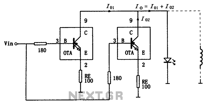
The high-speed parallel current drive circuit utilizes the OPA660 operational transconductance amplifier (OTA). An input signal, Vin, is connected to a 180-ohm resistor equivalent device at the base (pin 3) of the OPA660. The collector (pin 8) is directly...