
PWM Motor Control circuit

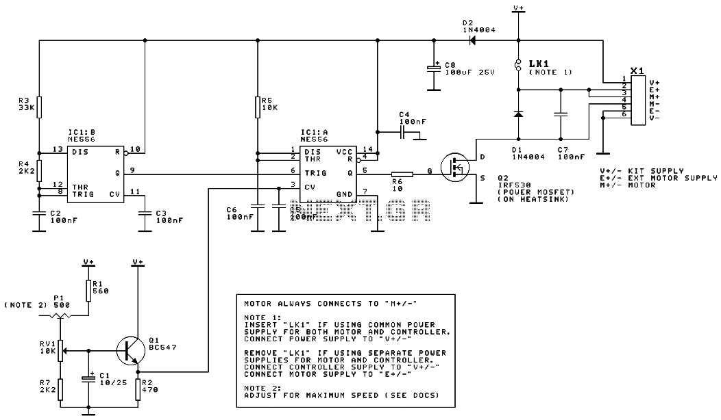
The 10kΩ resistor ensures the discharge pin is not left "floating," which is crucial when using a CMOS version of the 555. A potentiometer connected to the Control Voltage pin adjusts the internally set voltage by a potential divider. This alteration causes a change in the internal voltage compared to the capacitor voltage, resulting in the 555 switching earlier at lower Control Voltage pin voltages, leading to shorter output pulse widths and reduced power output per cycle. This side effect causes frequency variations, being higher at lower speeds and lower at higher speeds, with a frequency change of about a quarter, which is negligible except for the varying audio pitch of the motor.
At the output stage, the TIP122 functions as a Darlington-pair transistor amplifier with a gain of approximately 5000, theoretically requiring only 1mA from the 555 at a maximum load of 5A. However, in practice, more current is often drawn. For low currents around 200mA or less, a small heatsink may suffice, but a medium-sized heatsink rated at about 1W/K is necessary for higher loads. In worst-case scenarios, the TIP122 experiences a 4 Volt drop at 5 Amperes, resulting in 20W of power dissipation. Consequently, the heatsink must dissipate 20J of heat per second, with a temperature increase of 20K considered acceptable near room temperature (293K), remaining well below the 343K limit. This configuration can be adjusted for smaller loads as both current and voltage drop decrease. In extreme cases, a variable-voltage control unit could lead to the output transistor dissipating the entire output power of the system, necessitating a 5W/K heatsink, which is significantly larger and more costly.
The circuit includes a diode that protects against voltage spikes produced by the motor in the reverse direction. It is advisable to select a diode capable of handling higher currents, such as using a 1N5401 diode for motors that nominally draw 2A. The circuit should be powered by a smoothed DC supply, as regulation is not essential and may be counterproductive; the voltage drop through a regulator could exceed that of the output transistor.As this controller has been designed primarily for controlling model trains, it is designed to deliver around 12-15 Volts, although this system should work with as low a voltage as 3V (indeed it also works on a 6V supply to control some accessories I have). With regard to maximum current, the output stage should in theory be able to deliver around 5 Amperes, although I have never tested the unit beyond 2A.
The above diagram describes the electronic configuration of the controller. At its heart is the 555 timer/multivibrator Integrated Circuit (I.C.). This generates the pulses of varying widths. The 36kΩ resistor and 0.1μF capacitor set the mid-range frequency at 200Hz. If two controllers are required, the 556 dual timer circuit can be used in order to reduce the package count and overall circuit size. This circuit has been built and tested using the standard NE555/6 and the CMOS TS555 parts, all of which have been successful.
At the limits of the voltage range, strange effects occur at the output with the standard part; something which does not occur with the TS555. Note that the 10kΩ resistor just pulls up the discharge pin so it is not left "floating", and is particularly important if a CMOS version of the 555 is employed. The potentiometer connected to the Control Voltage pin varies the voltage set internally by a potential divder.
This causes the voltage internally compared with the voltage on the capacitor to be altered, thus at a lower voltage on the Control Voltage pin a lower capacitor voltage is needed, hence the 555 switches earlier. However as the voltage falls at the approximately the same rate, the output pulse width is relativly shorter, hence less power per cycle is output.
As a side effect, the frequency is higher at lower speed and lower at higher speeds as the rise time varies, and the fall time remains largely unaffected. This variation is of the order of about a quarter of the frequency, but since the frequency is not greatly important the resultant effect is neglegable (except for the varied audio pitch produced by the motor).
At the output stage, the TIP122 acts as a darlington-pair transistor amplifier with a gain of approximately 5000. This means that in theory only 1mA needs to be sourced from the 555 at the maximum 5A load. In practice more current is often drawn, however. At low currents of around 200mA or less, a small heatsink (or even no heatsink at all) will suffice. However a medium-sized heatsink of about 1W/K will be needed for higher loads (up the maximum). This is because for the worst case, the device will have a voltage drop of 4 Volts at a current of 5 Amperes this is a power of 20W.
Therefore the heatsink must be able to dissipate 20J of heat per second, with a suitable increase in temperature. An increase of 20K is satisfactory at a temperature near room temperature (293K) as this is well below the limit of 343K.
Of course, this can be varied backwards accordingly for smaller loads as both the current and voltage drop through the device decrease. (In the worst case, a variable-voltage control unit will cause the output transistor to dissipate the entire output power of the system, i.e.
90Watts. This, of course, requires a 5W/K heatsink which is about ten times the size due to the way in which heat flows, but will cost more still.) The diode in the circuit works by shorting out any voltage spikes produced by the motor in the reverse direction. Note that it is desirable to use a diode that can conduct a larger current with a much larger motor. For example if the motor nominally draws 2A of current, then a 1N5401 diode would be more suitable. The circuit should be powered from a smoothed DC supply. Regulation isn't essential, indeed it isn't desirable since the voltage drop through a regulator is likely to be more than that through the output transistor.
🔗 External reference
Related Circuits
This is the schematic diagram of a DC motor speed controller circuit. The circuit utilizes two oscillators/timers that are configured as a Pulse Width Modulator (PWM). The timer chip used in this circuit is a dual NMOS timer/oscillator. The DC...
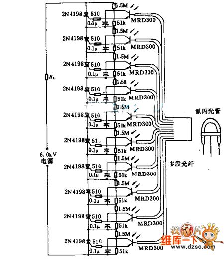
Light emitted by a Xenon flash tube is transmitted to the phototransistor MRD300 through an optical fiber. The sensitive current is amplified to trigger a series of thyristors simultaneously. Consequently, a high voltage of 6000V is applied to loader...
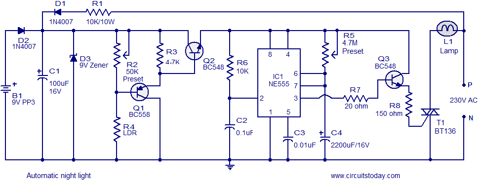
A simple and inexpensive automatic night light circuit designed using the timer IC NE555, which extinguishes after a preset time. This time can also be adjusted. The automatic night light circuit utilizes the NE555 timer IC configured in monostable mode....
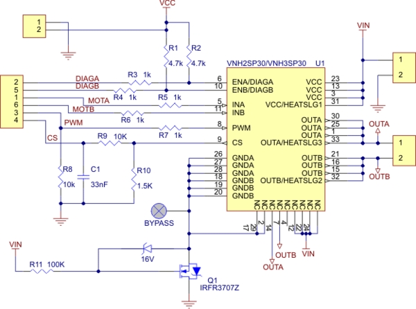
Need more current? If you have a larger motor ready for use, the Pololu High Current Motor Driver Board 14A 6V-16V is the ideal solution. Connect three digital lines to your microcontroller (five if error condition feedback is desired),...
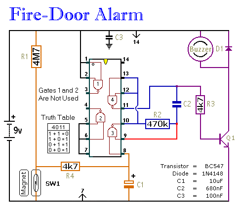
This circuit provides an alert when a door that should remain closed is left open. It is designed to be attached to a fire door, allowing normal passage. If the door remains open for more than 30 seconds, a...
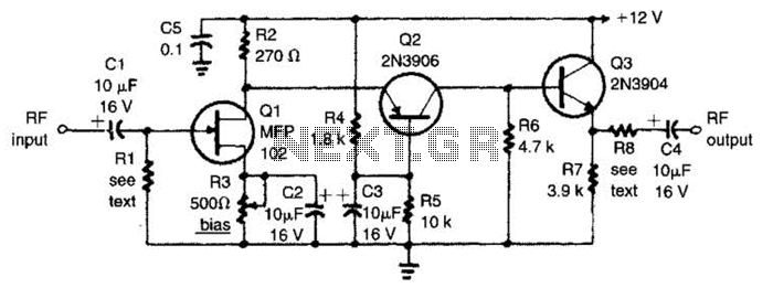
The circuit features a frequency response that spans from 100 Hz to 3 MHz, with a gain of approximately 30 dB. Field-effect transistor Q1 is arranged in a common-source self-biased configuration, and an optional resistor R1 is available to...