
PWM fan controller with PIC 12F675

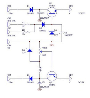
The circuit described involves a temperature sensing and control mechanism utilizing a temperature sensor (U2) placed in close proximity to the monitored item. The sensor's role is to detect temperature changes, which subsequently modulate the duty cycle of a motor. As the temperature rises, the control circuit will increase the duty cycle, allowing for proportional control over the motor's speed or power output.
The optical components D1 and R2 serve a dual purpose: providing visual feedback regarding the current duty cycle and enhancing user interaction with the circuit. D1, a blue LED, will illuminate in accordance with the duty cycle, allowing users to easily gauge the operational state of the motor. R2, likely a current-limiting resistor, ensures that the LED operates within its specified current rating, preventing damage.
The circuit utilizes Q1, a 2N4001 NPN transistor, as a switching element. This transistor will act as an interface between the control signal from the temperature sensor and the motor's power supply. When the temperature exceeds a predetermined threshold, the sensor activates Q1, allowing current to flow through the motor circuit, thereby increasing the motor's duty cycle. The choice of a 2N4001 transistor suggests that the circuit is designed for moderate power applications, given its voltage and current ratings.
All resistors in the circuit are specified as 1/4 Watt, indicating that they are suitable for low-power applications. This specification is critical for ensuring that the components can handle the power dissipation without overheating. Proper selection of resistor values will be necessary to fine-tune the performance of the LED and the transistor's switching characteristics.
Overall, this circuit design integrates temperature sensing with motor control and visual indication, creating an efficient and user-friendly monitoring system. Careful attention to component placement, power ratings, and circuit connections will be essential for optimal performance and reliability.The temperature sensor U2 needs to be located next to the item being monitored. As the temperature increases the motor duty cycle will increase. D1 and R2 are optical components, they only need to be installed for a visual indication of the current duty cycle. Q1 is a 2N4001 NPN transistor. Resistors are all 1/4 Watt. D1 is a blue LED. 🔗 External reference
Related Circuits
DC fan control circuit for a power amplifier. It features a variable speed DC fan that operates based on the input signal. The speed of the fan's rotation is dependent on the amplitude of the input signal received from...
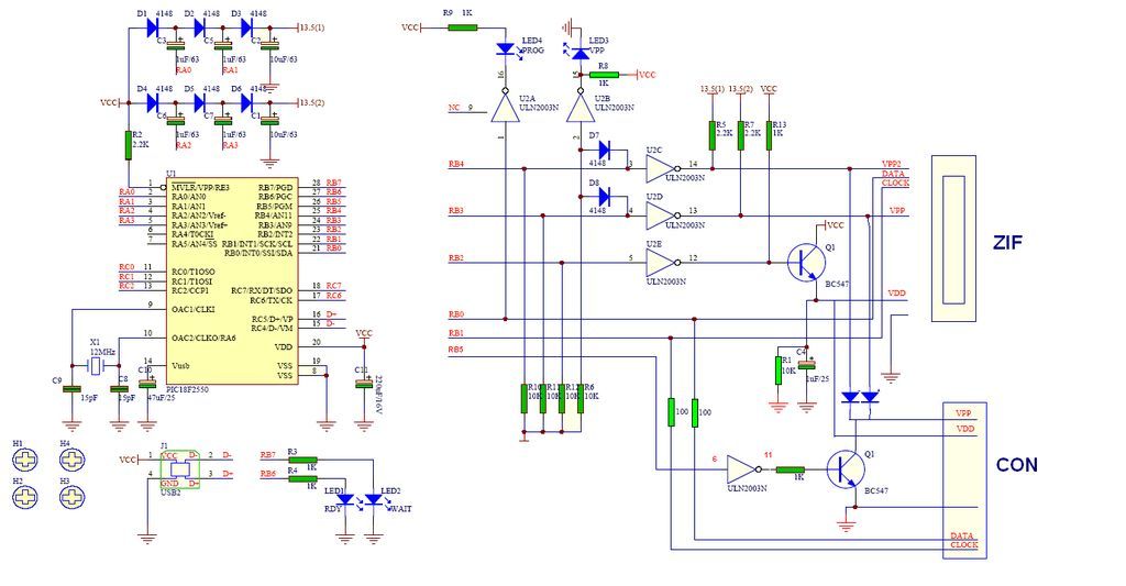
GTP USB PIC Programmer (Open Source). This project includes the GTP USB (not plus or lite). The schematic, photos, and PCB have been developed by PICMASTERS. The GTP USB PIC Programmer is an open-source device designed for programming PIC microcontrollers...
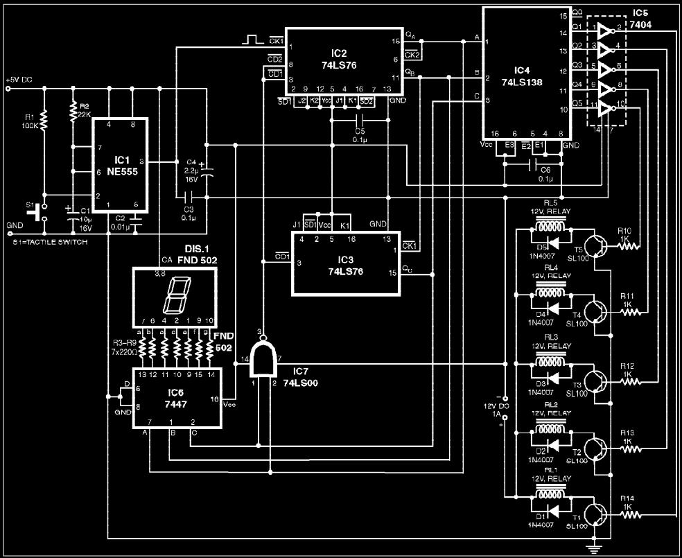
The circuit presented is a digital fan regulator that offers five speed levels, similar to conventional fan regulators. This ceiling fan controller utilizes readily available components. An optional 7-segment display with associated circuitry is included to show the selected...
This scanner uses a DDS circuit to scan through the frequency band. Since a DDS is used to set the desired frequency, this receiver can jump from one frequency to another within microseconds, making it very fast. The receiver...
A motor coil requires controllers to adjust its position and speed. A motor driver is necessary to amplify the low output current from a controller to a larger current required by the motor. The following article describes how to...
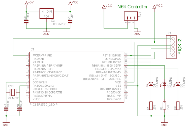
A few old N64 controllers were found, and the idea is to use them to control other devices. This document outlines the detailed steps taken to achieve this. A PIC microcontroller was utilized, although the code can be adapted...