
Timer circuit

The schematic design incorporates several key components that contribute to its functionality and reliability. The pushbutton switch SW1 serves as the user interface for initiating the timer, while the transistor TR1 acts as a relay driver, ensuring that the relay is activated with sufficient current. The inclusion of the diode D1 is critical for protecting the transistor from voltage spikes, which can occur when the relay coil is energized or de-energized. This diode effectively provides a path for the inductive kickback generated by the coil, thereby preventing damage to the transistor.
The choice of a 5V relay is significant, as it provides compatibility with the circuit's operating voltage. It is essential to select a relay that can handle the specific load being controlled, whether it is AC or DC, and to ensure that the relay's ratings are not exceeded during operation. The recommendation to maintain a safety margin is a prudent practice in circuit design, enhancing the longevity and reliability of the components.
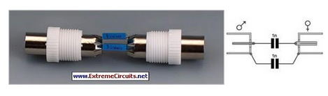
The ceramic resonator connected to the Nutchip is an integral part of the timing mechanism, providing a stable clock signal that ensures accurate timing operations. For applications requiring higher precision, a quartz oscillator could be integrated into the design, offering improved timing accuracy for more demanding applications.
The reset functionality, facilitated by the RC network of R2 and C2, allows for reliable circuit resets, which is crucial in applications where consistent performance is necessary. The assembly process is designed to be straightforward, allowing for efficient construction of the circuit on either a PCB or prototype board, depending on the builder's preference and available resources.
In conclusion, this schematic provides a versatile and reliable timer circuit that can be adapted for various applications through reprogramming of the Nutchip. The thoughtful selection of components, attention to safety, and consideration for ease of assembly contribute to a robust electronic design suitable for a range of timing tasks.The schematic diagram is quite straight forward. SW1 is a pushbutton used for starting the timer. The oputputs are set logic level 0 when the timer is not triggered, and to logic level 1 when the timer triggers. The relay driver transistor TR1, which receives its base current from Nutchip output OUT1 via the resistor R1, supplies enough current to energize the relay.
The diode D1, connected in parallel with relay`s coil, safeguards the transistor against the high voltage that builds up on the coil when it is energized or released. The relay is a 5V coil type, . and it must be choosen accordingly to the load you want to drive (e. g. AC or DC load). Ask your electrician for a suitable model, and always keep an generous safety margin (usually 50% or more) in excess the maximum specs declared by the manufacturer.
For example, it is safer not to surpass 500W for a relay specified for continuous 1000W load maximum by the manufacturer. The schematic shows a ceramic resonator connected to Nutchip pins 4 and 5. This kind of clock source ensures a timing accuracy usually better than 1%, which is suitable for most uses.
If you are looking for an even more accurate timer (e. g. for daily or weekly timers), a better choice is the quartz clock oscillator as shown in the base circuit collection. The same page shows alternate reset circuits that can be used when maximum reliability is required (this circuit uses a simplified RESET, the pin connects to the positive rail through an RC network made from R2 and C2).
The circuit is simple and can be assembled in just an hour if you have a printed circuit board (PCB). Alternatively you can use a prototype board, in that case it requires more time and patience to be completed.
Alwai start from smaller parts, leaving the bigger parts for later in order to have more space to work. Do not solder the Nutchip to the PCB, use a socket instead. Be very careful when placing the relay, ensure that the tracks for the relay switch have enough insulation (if necessary remove excess copper with a Dremel tool or a wire cutter).
Unintentional short circuits between the tracks from CN2 and the rest of the circuit can result in dangerous or lethal power discharges, besides destroying completely the circuit itself. Connector CN1 is required only if you are going to reprogram the Nutchip in-circuit, that is downloading a new truth table without removing it from the circuit, or if you want to use Nutchip Commander, the virtual remote control and debugger software.
Parts layout on the printed circuit board. You can build yours or use a prototype board: in the latter case, follow the gray grid (grid spacing is the same as the holes in a proto board), and solder bare copper wire to make the tracks. With just one circuit we can get a full assortment of timers, simply reprogramming Nutchip`s truth table.
Each of the following timers is designed to fit a specific purpose, with durations that spannig from few seconds to many hours. Pressing the button, this timer starts the relay immediately, and releases it precisely after the time set in the "timeout" row (state st01).
Pressing again the button has no effect, as long as the button is pressed inside the timeout interval. The timer starts its delay peri 🔗 External reference
Related Circuits
Nowadays, an increasing number of audio-visual devices in homes are interconnected. This is particularly true for televisions, which may be linked to DVD players. In modern home entertainment systems, the integration of various audio-visual devices enhances user experience and convenience....
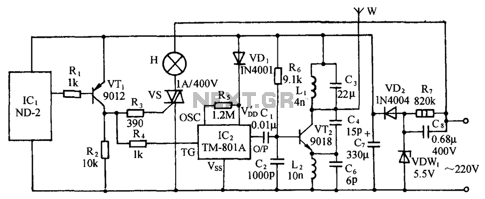
The circuit includes a comprehensive array of components such as vibration sensors, a follower, a lamp relay control circuit, a voice sounding circuit, a high-frequency oscillation circuit, and an AC rectifier buck power supply circuit. The vibration sensor is...
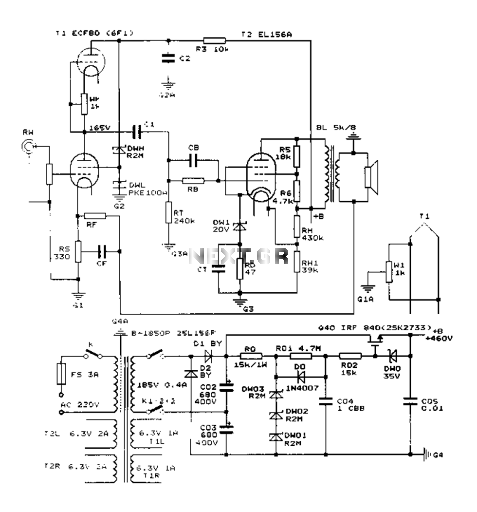
The Danji mellow sound is characterized by its transparent and natural quality, offering a sweet and sincere listening experience that is tireless over long durations and rich in humane color. Tube amplifiers have become an audiophile's companion and are...

This design circuit is for a digital voltmeter. The integrated circuit ICL7107 serves as a 3-1/2 digit LED analog-to-digital converter (A/D converter). It includes an internal voltage reference, high isolation analog switches, sequential control logic, and display drivers. An...
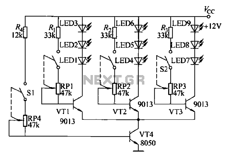
The circuit is designed to facilitate the teaching of color synthesis principles in color television, allowing students to better understand the concept through visual aids. It effectively reproduces color signals, thus simplifying the abstract nature of color synthesis. The...

The K-type thermocouple is a commonly used temperature sensor in industrial production and scientific experiments. It can measure temperatures ranging from 0 to 1300 degrees Celsius in various applications, including direct measurements of gas, liquid, and solid surfaces. Its...