
Pwm motor speed control

The described circuit operates by utilizing pulse width modulation to control the speed of a DC motor. The MGP20N45 TMOS devices serve as high-efficiency switches that modulate the power delivered to the motor based on the PWM signal's duty cycle. The PWM signal is generated by a microprocessor or digital logic circuit, which allows for precise control of the motor speed.
The comparator U1 is essential for comparing the PWM signal with a reference voltage, ensuring accurate timing and switching of the TMOS devices. The output from U1 is then sent to a set of paralleled inverters (U2, U3, and U4), which amplify the signal to ensure that the gates of the TMOS devices receive a sufficient drive voltage. This configuration helps in achieving rapid switching and minimizes power loss during operation.
The bridge rectifier D1 converts the AC input voltage to a DC output, ensuring that the motor receives a consistent power supply. The filtering components, R5 and C1, smooth out the rectified voltage, providing a stable DC supply to the motor and reducing voltage ripple.
The inclusion of the free-wheeling diode D3 is crucial for protecting the TMOS devices from voltage spikes that may occur when the motor is switched off. This diode allows for the safe dissipation of inductive kickback generated by the motor's coils, thereby preventing potential damage to the switching devices.
Furthermore, the back-to-back zener diode D2 serves as a protective measure against transient voltage spikes and high voltage surges that could otherwise exceed the voltage ratings of the components in the circuit. By clamping excessive voltages, D2 ensures the longevity and reliability of the circuit under varying operational conditions.
Overall, this circuit design effectively integrates PWM control, robust voltage regulation, and protective components to achieve efficient motor speed control while safeguarding against potential electrical hazards.Speed control is accomplished by pulse width modulating the gates of two MGP20N45 TMOS devices. Therefore, motor speed is proportional to the pulse width of the incoming digital signal, which can be generated by a microprocessor or digital logic. The incoming signal is applied to comparator Ul, then to paralleled inverters U2, U3, and U4 that drive the two TMOS devices, which, in turn, control power applied to the motor armature.
Bridge rectifier Dl supplies fullwave power that is filtered by R5 and Cl. Free-wheeling diode D3 (MR854) prevents high voltage across Ql and Q2. A back-to-back zener diode, D2, protects against transients and high voltage surges.
Related Circuits

To achieve a low-cost, accurate, and simple position control system, a stepper motor can be utilized. A circuit designed to drive the motor should be mounted in proximity to the motor itself. Stepper motors are widely employed in applications requiring...
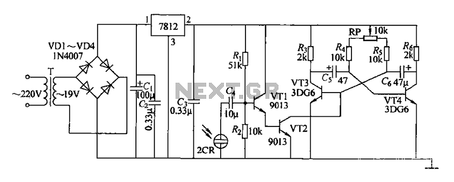
220V AC voltage is transformed by transformer T to 19V. After passing through a full-wave bridge rectifier and filter capacitor C, the voltage is regulated to DC using a 7812 voltage regulator. When the battery indicator light is illuminated,...
The following circuit illustrates the use of a 555 integrated circuit (IC) for an infrared (IR) remote control extender circuit. Features include support for 850 nm and 950 nm signal wavelengths, along with the capability to generate control pulses. The...
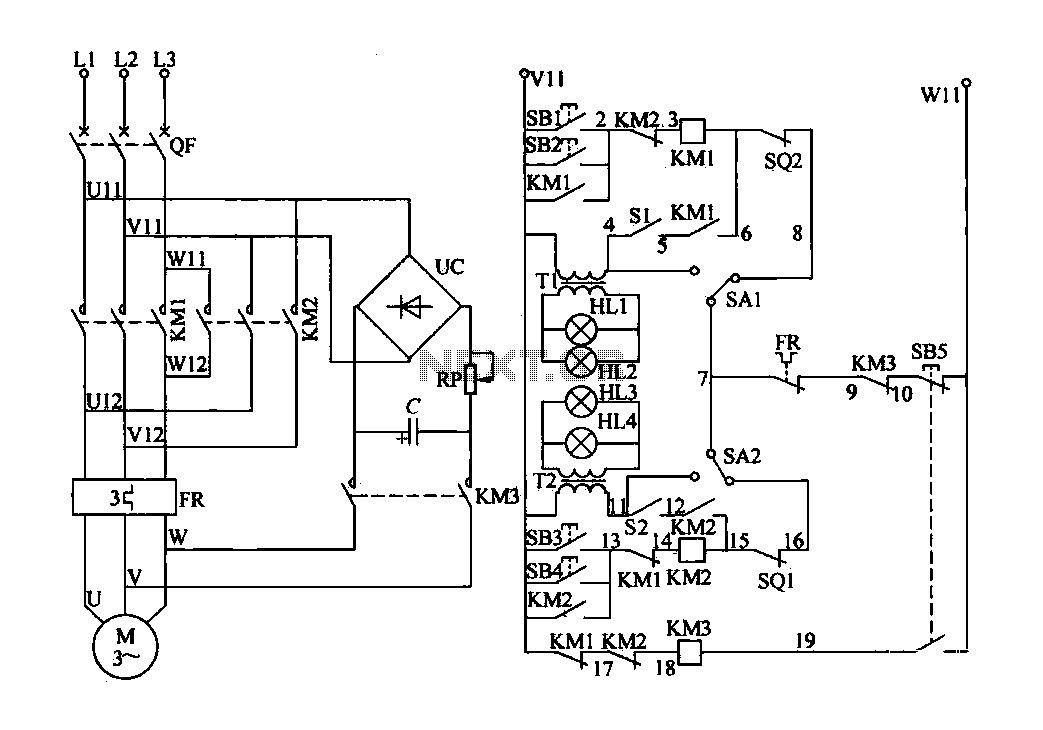
The electric valve control circuit consists of three main parts: the main lines, control lines, and power consumption brake line. The main circuit includes a power switch (QF), three-phase AC contactors (KM1, KM2), a thermal relay (FR), and a...

This is a BTL (bridged tied load) mono amplifier with a DC volume control circuit. This circuit utilizes the TDA7052A/AT, which is suitable for monitors, TVs, and battery-operated portable radios and recorders. Unlike conventional DC volume circuits, the TDA7052A/AT...
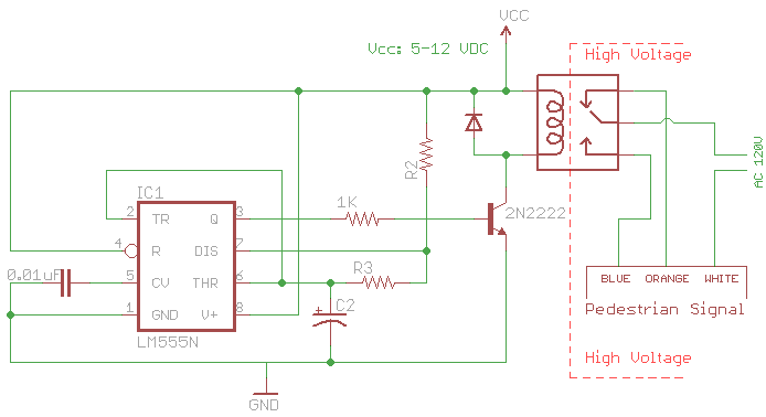
The signal consists of three wires: common, "walk," and "don't walk." This document outlines the operation of the unit's countdown feature. The information and examples provided here are applicable to other models and brands of signals. The signal was...