
Two Wires-Stepper Motor Controller

Stepper motors are widely employed in applications requiring precise control of angular position, velocity, and acceleration. They operate by dividing a full rotation into a series of discrete steps, allowing for fine control over movement. The driving circuit for a stepper motor typically consists of a microcontroller or a dedicated driver IC that sends pulse signals to the motor coils in a specific sequence, enabling the motor to rotate in precise increments.
A common configuration for the drive circuit involves using an H-bridge arrangement, which allows for bi-directional control of the motor. This setup enables the motor to rotate clockwise or counterclockwise based on the polarity of the signals applied to the motor windings. The circuit should also include current limiting resistors or a current sensing mechanism to prevent overheating and ensure the longevity of the motor.
To enhance accuracy, feedback mechanisms such as encoders can be integrated into the system. These devices provide real-time position data, allowing for closed-loop control, which adjusts the motor's operation based on the actual position versus the desired position. The design should also consider power supply requirements, ensuring that the voltage and current ratings meet the specifications of the stepper motor being used.
In summary, the implementation of a stepper motor control circuit involves careful consideration of the driving method, feedback mechanisms, and power supply, all contributing to an effective and reliable position control system.To get a position control that are low cost, accurate and simple we can use stepper motor. To drive it we can use a circuit mounted close to the motor, and to.. 🔗 External reference
Related Circuits
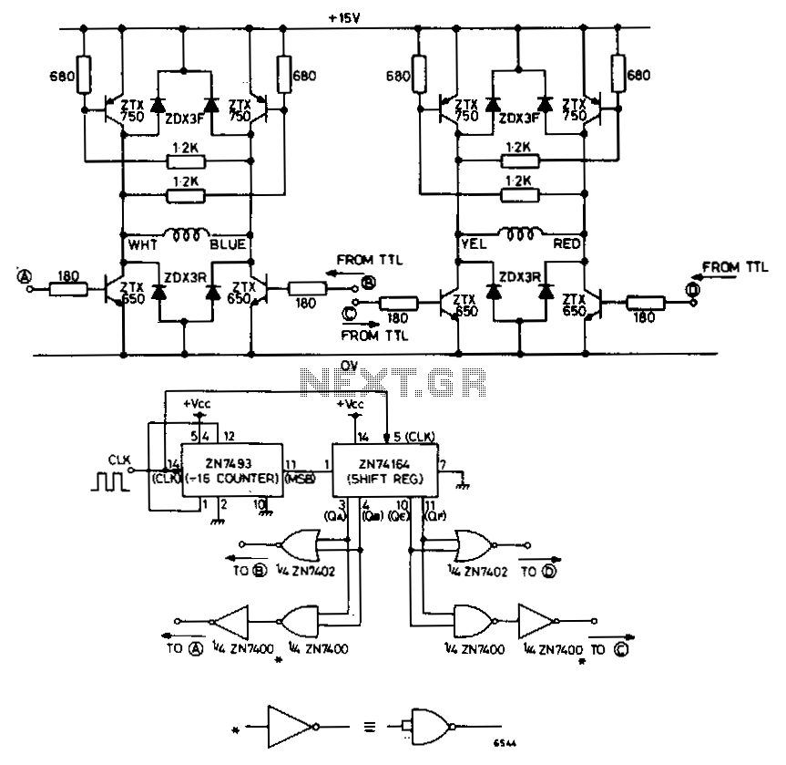
The circuit depicted in Fig. 62-15A is intended to drive a 15-V, two-phase, bipolar stepping motor, delivering a bidirectional single-level voltage across each winding with currents reaching up to 9.6 A. It comprises two identical transistor bridge stages that...
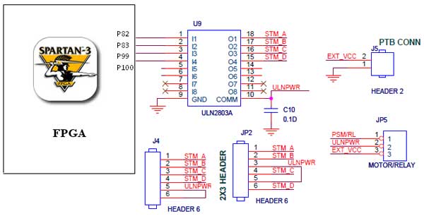
The Spartan-3 Primer board features external stepper motor interfacing, as illustrated in the accompanying figure. The stepper motor is driven by a ULN2803A, which is a high-voltage, high-current Darlington transistor array. The ULN2803 is utilized as a driver for...
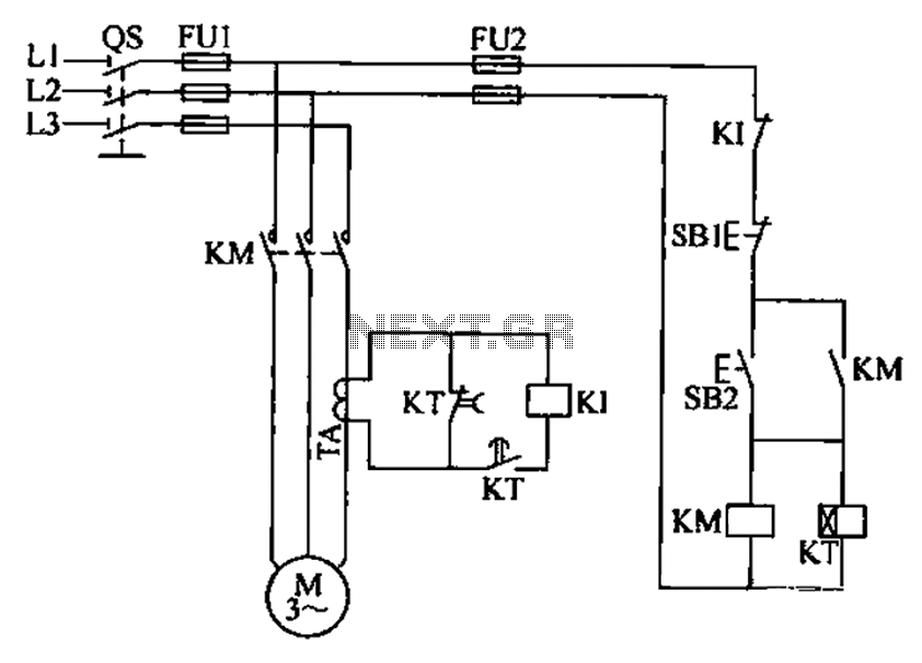
A three-phase electric motor overcurrent protection circuit. This example circuit utilizes a transformer to monitor the current, ensuring that the currents in the three-phase motor do not exceed normal operating levels. When the current exceeds the set threshold, the...
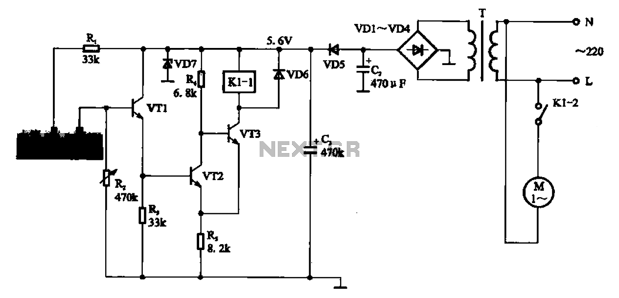
AC motor control circuit for a sprinkler. If the circuit involves an AC motor, it can be designed according to the connection shown in the figure, detailing the work process and the underlying principles of the circuit. The AC motor...
The 8051 microcontroller features a transmit channel and a receive channel for serial communication. The transmit data pin (TXD) is designated as P3.1, while the receive data pin (RXD) is located at P3.0. The serial signals on these pins...
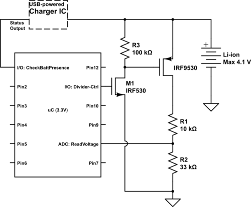
Currently using the PIC24FJ128GA010, there is a plan to utilize an Input/Output port to connect a 4.2 V LiPo battery and monitor the voltage to ensure it does not drop below 3.7 V. It is advised to avoid digital...