
QRD1114IR Sensor

The circuit utilizes a PIC18F452 microcontroller, configured for ADC operations with a 10-bit resolution. The oscillator frequency is set to 20 MHz, and the ADC clock source is defined as RC. The sampling time for the ADC is established at 50 microseconds. The TRISA register is set to all inputs, allowing for analog readings on PORTA. The ADCON1 register is configured to set PORTA as analog input, with the output justified to the right.
The main program loop begins by reading the ADC value from channel 0 into the variable adcVar. The serial output on PORTC.6 displays the decimal value of adcVar, followed by a carriage return. The duty cycle for PWM control is calculated based on adcVar, with two different code configurations available. In the first configuration, the duty cycle is set directly proportional to adcVar, while in the second configuration, it is inversely proportional, allowing for flexible control of LED brightness based on the detected distance from the sensor. This setup enables effective object detection and surface differentiation in various applications, including robotics and automation systems.Initially I chose another infrared sensor for test, PIR Motion Sensor, which was to detect any motion in front of the sensor but it turened out not so sensitive. So that I looked at this QRD1114 IR Sensor for substitute. In this test, I used both as digital and analog input to see what difference it has and how sensitive it is.
Object or surfaces must be within 0. 5cm. This circuit will not distinguish between white and black objects but it will let you know when you are at the edge of a surface. If you want to detect the difference between white or black surfaces, in the circuit the Input pin on the Micro should be an analog to digital converter or some other device that can utilize variable voltage levels. A black surface will give a voltage some where between 0V and 5V and white surfaces will give a voltage of 5V.
Determining the voltage level for your black and white surfaces will require experimentation. I have tested object/surface detection and stiil try to figure out Black/White difference detection. Here is the schematic of how I hooked up QRD1114 IR Sensor to PIC18F452. Portd. 1 is used for digital input from QRD1114 IR Sensor`s signal while portb. 7 is for output to light a LED. Here I use PWM to let LED light gradually. The lighness depends on the variable "adcVar", which is in direct-ratio (code 1) or inverse-ratio (code 2) to the distance between reflecting surface and the sensor. In code one, when the reflecting surface is out of the range (0. 5cm), the sensor will read adcVar in the maximum (It should be 1023 in theory but it`s 1016 in fact. Also, the minimum is 30 instead of 0. DEFINE OSC 20 DEFINE ADC_BITS 10 ` Set number of bits in result DEFINE ADC_CLOCK 3 ` Set clock source (3=rc) DEFINE ADC_SAMPLEUS 50 ` Set sampling time in uS TRISA = %11111111 ` Set PORTA to all input ADCON1 = %10000010 ` Set PORTA analog and right justify output portb.
7 adcVar VAR word dutyCycle var byte main: ADCIN 0, adcVar serout2 portc. 6, 16468, [DEC adcVar, 13] dutyCycle = adcVar/5 pwm portb. 7, dutyCycle, 10 goto main DEFINE OSC 20 DEFINE ADC_BITS 10 ` Set number of bits in result DEFINE ADC_CLOCK 3 ` Set clock source (3=rc) DEFINE ADC_SAMPLEUS 50 ` Set sampling time in uS TRISA = %11111111 ` Set PORTA to all input ADCON1 = %10000010 ` Set PORTA analog and right justify output portb. 7 adcVar VAR word dutyCycle var byte main: ADCIN 0, adcVar serout2 portc. 6, 16468, [DEC adcVar, 13] dutyCycle = (1023-adcVar)/5 pwm portb. 7, dutyCycle, 10 goto main 🔗 External reference
Related Circuits
The following circuit illustrates a LEGO Light Sensor Circuit Diagram. This circuit is based on the LM358 integrated circuit, which features a dual operational amplifier and high-speed capabilities. The LEGO Light Sensor Circuit utilizes the LM358, a versatile dual op-amp...
To obtain an accurate pressure value, it is essential to eliminate offset errors. Numerous basic circuit designs are employed to remove these offset errors. Offset errors in pressure measurement systems can lead to inaccuracies in the readings, which may affect...
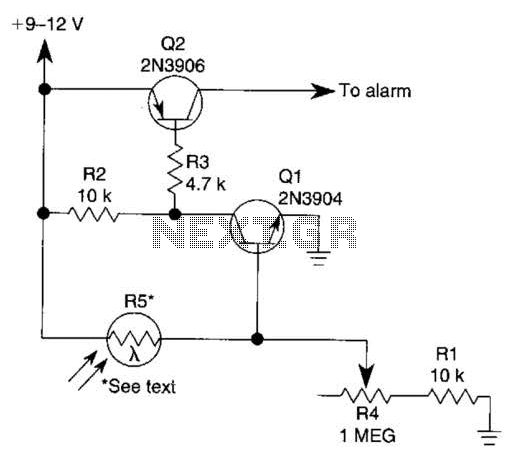
The circuit functions as a sensor capable of triggering an alarm without direct contact from an intruder. It utilizes a visible or invisible light source that illuminates the sensor, maintaining the detection loop in a normally closed state. As...
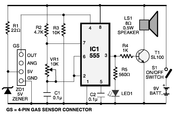
This schematic diagram represents an LPG gas leakage sensor alarm circuit powered by a 9V PP3 battery. A Zener diode (ZD1) is utilized to convert the 9V input into 5V DC, which is required to operate the gas sensor...
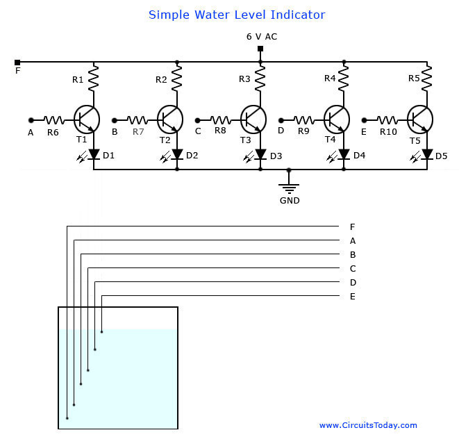
A simple water level indicator project with a circuit diagram for home and industry. This water tank level sensor can be utilized for any liquid level indicator projects. The water level indicator circuit is designed to monitor and display the...
Irisys offers a selection of five thermal imaging temperature sensors that utilize a 16G—16 pixel array, providing various options for temperature range, accuracy, and measurement angle. The IRI 1041, IRI 1051, and IRI 1061 models are identical to the...