
LEGO Light SensorCircuit With LM358 IC

The LEGO Light Sensor Circuit utilizes the LM358, a versatile dual op-amp IC, to create a light detection system suitable for various applications, particularly in robotic and automation projects using LEGO components. The circuit typically includes a light-dependent resistor (LDR) that changes its resistance based on the intensity of ambient light. This change in resistance is fed into one of the op-amps in the LM358, which is configured as a voltage comparator.
In this configuration, the LDR is connected to a voltage divider circuit, allowing it to produce a varying output voltage that corresponds to the light level. The second op-amp can be used to amplify the signal from the LDR or to provide additional processing, such as filtering or further comparison against a reference voltage. The output of the first op-amp can be connected to an LED or another actuator, enabling the circuit to respond to changes in light conditions.
This circuit can be employed in various applications, including automatic lighting systems, light-following robots, or as part of a larger LEGO robotics project. The simplicity of the LM358 allows for easy integration and modification, making it a popular choice for hobbyists and educators looking to explore the principles of electronics and sensor applications.The following circuit shows about LEGO Light Sensor Circuit Diagram. This circuit based on the LM358IC. Features: dual opamp,high speed double .. 🔗 External reference
Related Circuits
The circuit is quite simple and can be utilized as an introductory hardware modification for the NXT platform. A white LED (D1) is powered through a 150-ohm resistor (R1) using the 4.3V power supply from the NXT. The forward...
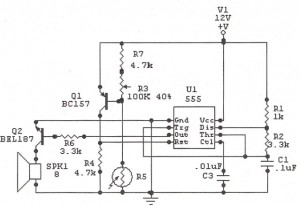
The IC 555 Light Alarm (Sun Up Alarm) circuit is designed to emit a loud alarm at dawn, particularly for individuals who struggle to wake up, even with a traditional alarm clock. The circuit is modifiable. The IC 555 timer...
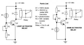
The potentiometer adjusts the trigger level. The diode in the circuit diagram is specified as 1N914, which is suitable for light-duty relays; however, since the 1N914 is a signal diode, it is not ideal. A 1N4001 or a better...
This simple flashing light circuit operates at 6 volts and 0.5A, exhibiting low current consumption when the light bulb is turned off. The frequency of the flashing is predetermined. The circuit consists of a power supply, typically a battery or...
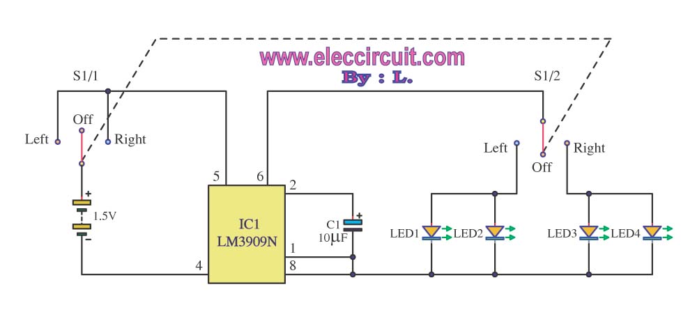
A bicycle typically does not have a turning light. When a cyclist wants to turn, it can be dangerous as vehicles following may not be aware of the turn. To enhance safety, a turning light circuit for bicycles can...
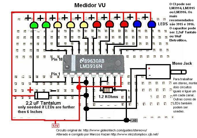
A post related to a do-it-yourself project for creating a VU meter and homemade rhythm lights that are easy to assemble. The project involves designing and constructing a visual audio level meter (VU meter) that responds to sound levels, as...