
QRP Antenna Tuner

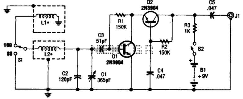
The described QRP antenna tuner, or transmatch, is designed to facilitate efficient power transfer from a low-power transmitter to a variety of antennas across the shortwave amateur radio bands, specifically from 3 MHz to 30 MHz. The primary function of this circuit is to match the impedance of the transmitter, which is conventionally 50 ohms, to the potentially mismatched impedance of the connected antenna. This impedance matching is crucial for optimizing signal transmission and minimizing signal loss due to reflections.
The core components of the circuit include a variable inductor and a variable capacitor. The variable inductor is placed in series with the transmission line, allowing for adjustment of the inductive reactance to match the antenna's impedance. The variable capacitor is connected to ground and is used to adjust the capacitive reactance. By tuning these two components, the user can achieve resonance at the desired frequency, which maximizes the power transfer to the antenna.
In practical implementation, the circuit is typically connected to a standing wave ratio (SWR) meter. The SWR meter provides real-time feedback on the impedance matching quality, indicating whether the circuit is tuned correctly. An SWR value of 1:1 indicates perfect matching, while higher values suggest a mismatch that could lead to power loss or damage to the transmitter.
The design of the circuit allows for versatility, accommodating a wide range of antenna types and configurations. This adaptability is particularly beneficial for amateur radio operators who may utilize various antennas for different bands and conditions. The construction of the tuner can be achieved using standard electronic components, making it accessible for hobbyists and engineers alike.
Overall, this QRP antenna tuner circuit exemplifies a fundamental tool in amateur radio, enhancing communication capabilities by ensuring efficient power delivery to antennas across a broad frequency spectrum.This circuit is for a QRP (low power) antenna tuner, a.k.a. a transmatch, for use in the short wave amateur radio bands from 3-30 Mhz. It allows a wide variety of antennas to be connected to a low power transmitter. When the circuit is properly tuned, the maximum transmitter power will be delivered to the antenna. It is used in conjunction with a standing wave ratio (SWR) meter. This is a fairly generic antenna tuner circuit. The purpose of a transmatch is to match the impedance of a transmitter, typically 50 ohms, to an unknown antenna impedance. The circuit consists of a variable series inductor followed by a variable capacitor to ground. Most transmitter outputs consist of 🔗 External reference
Related Circuits
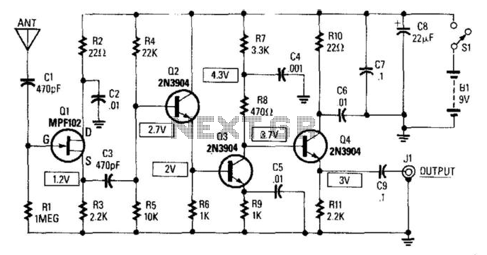
This circuit provides a gain of 14 to 20 dB at frequencies ranging from 10 kHz to 30 MHz. The antenna length can vary between 5 and 10 feet, with a 102-inch CB whip being particularly suitable for this...
This antenna may assist in minimizing power-line noise. It consists of a plastic hula hoop or conduit with a diameter of 3 feet, which is covered with aluminum foil to serve as a shield for LI and L2. LI...
This sensitive FM radio tuner is an ideal circuit for hobbyists who wish to construct their own tuners rather than purchasing a pre-assembled product. The FM radio tuner circuit is designed to receive frequency modulation signals, providing a clear and...

Got no dough for a commercial WiFi antenna? Looking for an inexpensive way to increase the range of your wireless network? A tin can waveguide antenna, or Cantenna, may be just the ticket. This design can be built for...
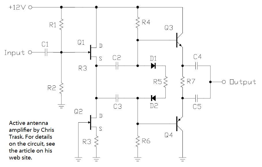
In the pursuit of effective small antennas, an active whip antenna was constructed. This compact vertical antenna is linked to a preamplifier, which serves to convert the high impedance of the 50-ohm receiver and coaxial cable. Various designs exist...
The circuit is a simple, but accurate Digital Guitar Tuner. It samples the input, which can be directly from the mics of an electric guitar, or from a microphone, if you're using an acoustic guitar. It can of course...