
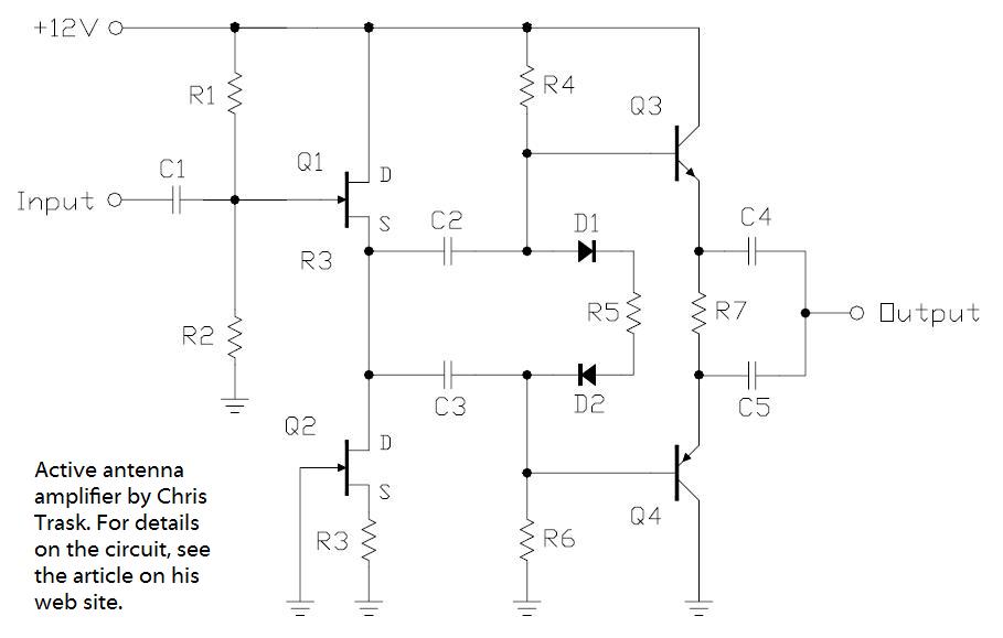
Active Antenna Ii

The described circuit is a high-frequency amplifier designed to enhance signal strength for radio frequency (RF) applications, specifically within the 10 kHz to 30 MHz range. The gain specification of 14 to 20 dB indicates that the circuit can effectively amplify weak signals, making it suitable for use in communication systems, amateur radio setups, or other RF applications where signal integrity is crucial.
The choice of antenna length, which can be adjusted between 5 and 10 feet, is significant for optimizing performance across the specified frequency range. A 102-inch CB whip antenna is recommended due to its design, which is well-suited for capturing and transmitting signals within the desired frequency spectrum. The length of the antenna plays a crucial role in determining the resonance and efficiency of the system, impacting overall gain and signal quality.
In constructing this circuit, careful consideration should be given to the amplifier design, including the selection of appropriate transistors or operational amplifiers that can handle the specified frequency range while providing the required gain. Additionally, the circuit layout should minimize losses due to parasitic capacitance and inductance, which can degrade performance at higher frequencies.
Power supply design is also essential, as the circuit must maintain stable operation across varying input conditions. Proper filtering and decoupling capacitors should be employed to ensure that the amplifier operates without interference from power supply noise.
In summary, this circuit is an effective solution for RF signal amplification, with specific attention to antenna design and circuit stability, making it a valuable component in various communication and broadcasting applications. This circuit provides 14- to 20-dB gain at frequencies from 10 kHz to 30 MHz. The antenna length can be anything between 5 and 10 feet. A 102-inch CB whip is excellent for this purpose.
Related Circuits
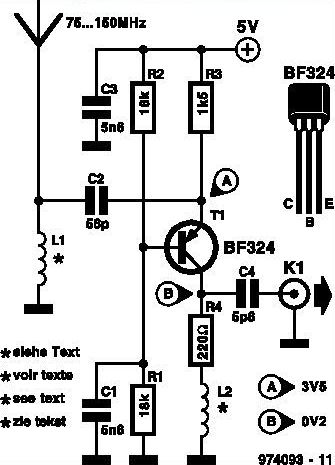
This inexpensive FM radio receiver antenna booster utilizes the BF324 TO92 style PNP transistor in a grounded-base configuration. The circuit can be employed as a... The FM radio receiver antenna booster circuit is designed to enhance the reception capabilities of...
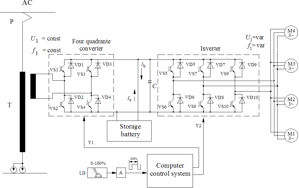
The diagrams illustrate the startup sequence of the TEP-60 diesel engine starter in relation to current accumulators: 1 - battery current without a supercapacitor block (SCB) when the traction generator operates in starter mode; 2 - battery current with...
A use has been found for a collection of DIP-style RF relays acquired from a discount electronics shop. These relays are completely sealed and RF shielded, featuring low contact capacitance, making them suitable for VHF frequencies. They operate at...

This is a low-cost FM antenna booster designed to enhance reception of programs from distant FM stations. The FM antenna booster circuit features a common-emitter tuned RF preamplifier utilizing the VHF/UHF transistor 2SC2570 (C2570). The schematic illustrates the configuration...
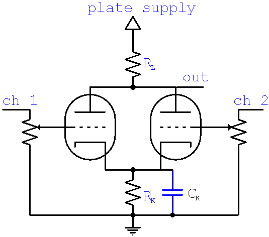
The calculator computes the gain and output impedance of a common plate load mixer. Each input channel controls a separate grid, which affects the plate current through the common plate load resistor RL and the cathode resistor RK. The...
In the pursuit of effective small antennas, an active whip antenna was constructed. This compact vertical antenna is linked to a preamplifier, which serves to convert the high impedance of the 50-ohm receiver and coaxial cable. Various designs exist...