
Quadrature Sinewave Oscillator

The quadrature oscillator is commonly used in various applications such as signal processing, communications, and control systems. It operates on the principle of generating two sinusoidal outputs that are orthogonal to each other, which is essential for tasks like modulation and demodulation in communication systems.
Typically, a quadrature oscillator circuit may utilize operational amplifiers, resistors, and capacitors to achieve the desired phase shift between the output signals. The operational amplifiers are configured in a feedback loop that stabilizes the oscillation frequency while ensuring that the output signals maintain the required phase relationship.
In a standard configuration, the oscillator consists of two identical RC networks that are connected to the inverting and non-inverting inputs of the operational amplifiers. The phase shift introduced by these RC networks is crucial; each stage of the network contributes to the total phase shift, ultimately resulting in one output signal being delayed by 90 degrees relative to the other.
The frequency of oscillation can be determined by the values of the resistors and capacitors used in the circuit. By adjusting these components, the frequency can be fine-tuned to meet specific application requirements. Additionally, the output signals can be further processed or amplified depending on the intended use.
Overall, the quadrature oscillator serves as a vital component in various electronic systems, providing essential functionality where phase relationship and signal integrity are critical.Quadrature oscillator is another type of phase shift oscillator. This circuit produce two sine wave signal. One of them is shifted 90 degree from the other.. 🔗 External reference
Related Circuits

This is a circuit known as a Wien bridge oscillator circuit. The circuit features both positive and negative feedback loops and operates under the control of an operational amplifier (op-amp). The oscillation frequency is determined by the RC time...
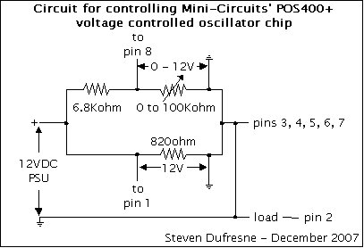
This is a UHF oscillator circuit designed to utilize the Mini-Circuits POS-400+ voltage-controlled oscillator chip. By applying a voltage between 0 to 12V on pin 8, it produces a sine wave output ranging from 200MHz to 380MHz on pin...
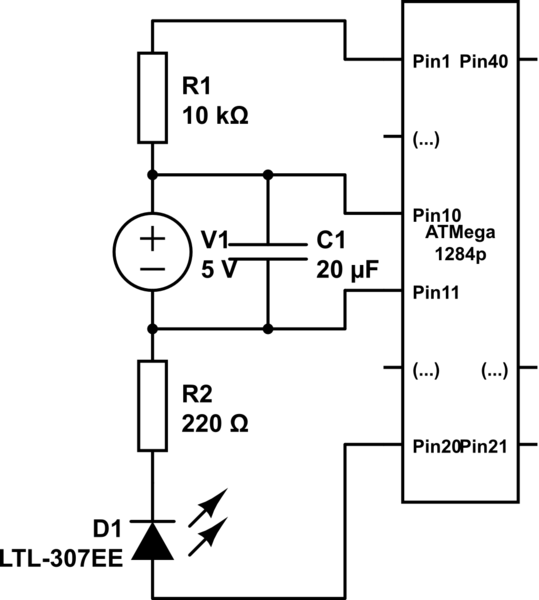
Program an ATmega1284P using an AVR Dragon and the Arduino IDE. The mighty1284p library has been installed, and after writing the sketch, it is compiled using the Arduino IDE. The compilation process creates a hex file in a temporary...
Here is a simple triangle/squarewave generator using a common 1458 dual op-amp that can be used from very low frequencies to about 10 Khz. The time interval for one half cycle is about R*C and the outputs will supply...
This circuit is a low-frequency Wien bridge sinusoidal oscillator designed for the audio range, characterized by very low distortion, making it suitable for testing various audio equipment. The circuit has undergone thorough testing, and a printed circuit board (PCB)...
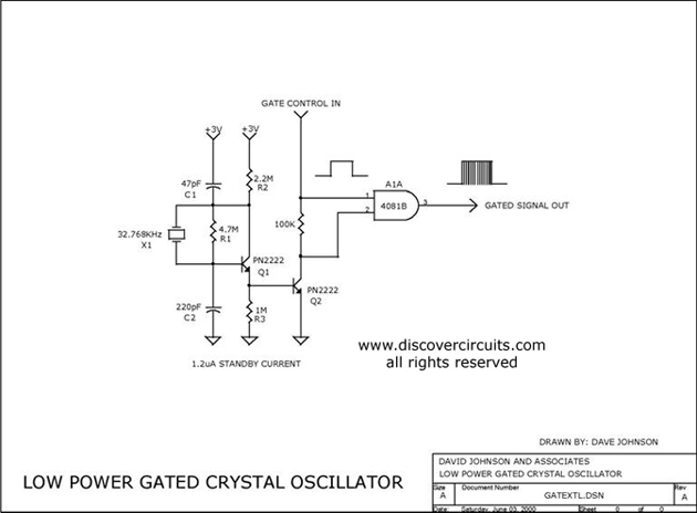
The circuit controls the output of a continuously operating 32KHz crystal oscillator, directing it to the input of a C-MOS buffer when clock pulses are required. This technique addresses the issue of a slow-starting crystal oscillator by maintaining the...