
Triangle / Squarewave Oscillator

The described circuit utilizes the dual operational amplifier (op-amp) configuration of the 1458 to generate both triangle and square waveforms. The operation primarily relies on the charging and discharging characteristics of a capacitor in conjunction with resistors, which determine the frequency and shape of the output waveforms.
In this application, the time period of the output waveforms is contingent upon the resistor-capacitor (R-C) time constant, where the frequency \( f \) can be approximated as \( f = \frac{1}{T} = \frac{1}{2RC} \). The capacitor charges through a resistor to create a ramp voltage, producing a triangle wave when the op-amp's output is fed back into the inverting terminal. The non-inverting terminal is typically set to a reference voltage, often ground, to establish a baseline for the waveform.
The amplitude of the triangle wave can be adjusted by varying the resistance value of the 47K resistor in the circuit. Increasing the resistance will result in a lower amplitude, while decreasing it will yield a higher amplitude, allowing for flexibility in application needs. To eliminate any DC offset present in the output waveform, a capacitor can be introduced in series with the output. This capacitor blocks any DC component, ensuring that only the AC signal is passed to the load or subsequent stages in the circuit.
The output stage is capable of supplying approximately 10 milliamps of current, which is adequate for driving light loads or interfacing with other circuits. It is essential to consider the power supply voltage and ensure that it is within the operational range of the 1458 op-amp to maintain proper functionality.
Overall, this triangle/square wave generator circuit is a versatile tool in electronics, suitable for various applications such as signal generation, waveform shaping, and modulation tasks.Here is a simple triangle/squarewave generator using a common 1458 dual op-amp that can be used from very low frequencies to about 10 Khz. The time interval for one half cycle is about R*C and the outputs will supply about 10 milliamps of current.
Triangle amplitude can be altered by adjusting the 47K resistor, and waveform offset can be removed by adding a capacitor in series with the output. 🔗 External reference
Related Circuits
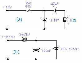
These two circuits are interesting from an academic point of view. Their practical implementation is rather critical and it is not easy to get steady operation. Circuit (a) requires a "cooked" zener: connect it first to a constant current...
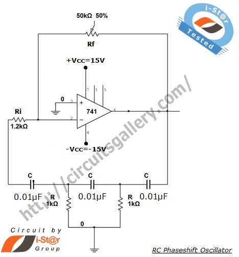
A phase-shifted oscillator can be constructed using a basic operational amplifier (op-amp), three resistors, and three capacitors. One of the resistors should be adjustable, while the other components should have the same value. This oscillator design exhibits low distortion...
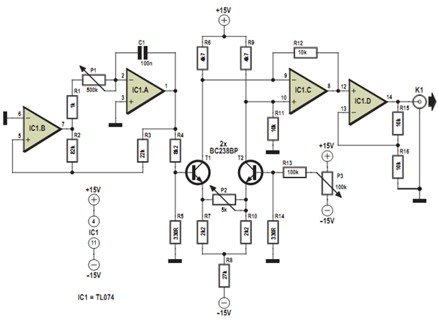
This design was developed to partially replace the well-known 8038 chip, which is no longer in production and therefore difficult to obtain. An existing design for driving a Linear Variable Differential Transformer (LVDT) sensor utilized the 8038 as a...
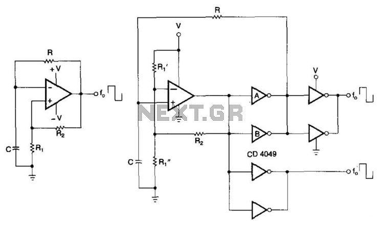
CMOS buffers added to an operational amplifier oscillator enhance performance, primarily due to the asymmetry and variability of the operational amplifier's output saturation voltages. The integration of CMOS buffers into an operational amplifier (op amp) oscillator circuit serves to significantly...
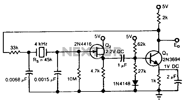
The Pierce circuit oscillates at 4 kHz. At low frequencies, the crystal's internal series resistance Rs is quite high (45 kΩ at 4 kHz). Therefore, an FET-based source follower is included to prevent Q1 from loading the crystal output. The...
The circuit operates in a parallel-fed configuration, as the DC plate current does not pass through the inductor. R3 can be substituted with an RF choke if desired. Capacitor C3 prevents B+ from appearing across the variable capacitor, which...