
Quick and Easy Wireless Circuit

The Quick and Easy Wireless circuit operates on a straightforward design that integrates essential components for wireless communication. The 7805 voltage regulator is a critical part of this circuit, providing a consistent +5V output from a +9V battery source. This regulator ensures that the microcontroller and other devices operate within their required voltage range, preventing potential damage due to overvoltage.
The filtering capacitor, rated at 47µF, is strategically placed to smooth out any voltage fluctuations, thereby enhancing the stability of the power supply to the circuit. This is particularly important in wireless applications where power supply integrity can directly affect performance.
The 18F452 microcontroller serves as the central processing unit of this circuit, managing the logic and control aspects. It receives input signals from the transmitter and processes them to control various output devices, such as LEDs and motors. The microcontroller operates on a digital logic level, interpreting the signals received and executing commands based on pre-defined programming.
The RC Transmitter is designed to send specific signals wirelessly to the receiver. It operates independently, generating two output signals that are sent to the PIC. The schematic does not include the transmitter, as it functions separately from the main circuit but is essential for the wireless communication aspect.
On the receiving end, the RC Receiver module connects to the microcontroller via PORTC, facilitating communication between the two. The receiver is powered by the same supply voltage as the PIC, ensuring compatibility and simplifying the overall circuit design. Two signal lines from the receiver connect to the microcontroller, allowing it to interpret the incoming signals and respond accordingly.
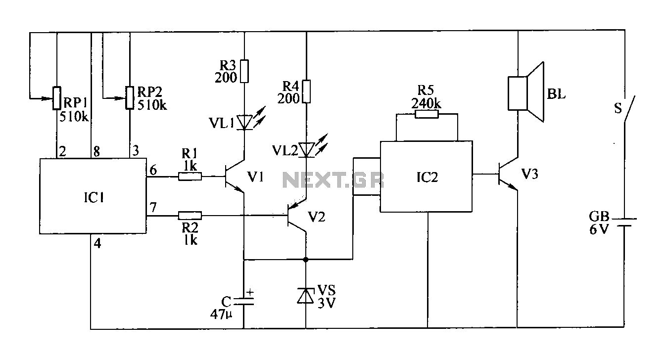
Overall, this wireless circuit exemplifies a simple yet effective design for remote control applications, combining reliable power management with efficient signal processing capabilities. The careful arrangement of components and the integration of wireless technology make it suitable for various practical applications.The Quick and Easy Wireless circuit is not terribly difficult however it will take some double checking to make sure you have everything hooked up properly before working the first time. The main devices used in the circuit are the 7805, 18F452, RC Receiver and RC Transmitter. The 7805 regulates the +9v battery down to +5v which the PIC and al l other devices want to see. The DC filtering capacitor used is 47uF and after this cap all devices are ready to see the power supply. The microcontroller circuit is where the input and output control is happening. The transmitter has two output signals going to the microcontroller, which get interpreted and then passed on to control the output devices (LED/Motor).
The transmitter is its own stand-alone device that transmits certain types of signals that the receiver understands and outputs, so it doesn`t appare on the schematic. The Receiver module, however, does connect to the PIC on PORTC so we can see that the receiver uses the same power supply as the pic and two signal lines are connecting to it as well.
🔗 External reference
Related Circuits
This circuit gradually illuminates a 120VAC lamp over an approximate 20-minute period. A bridge rectifier converts the AC voltage to 120V DC, supplying power to the MOSFET and the 60-watt lamp. A 6.2K, 5-watt resistor along with a Zener...
The double-limit temperature alarm circuit consists of a temperature detection control circuit, a temperature indicating circuit, and an alarm sound circuit. The components selected include resistors R1 to R5, which should be 1/4W metal film or carbon film resistors....
The current loop interface circuit diagram of the AD694 multi-functional sensor signal conditioner is utilized as a digital-to-analog converter (DAC). This current loop interface enables the conversion of digital values into voltage and subsequently into current signals. The circuit...
Short circuits or broken PCB tracks can be easily identified using a multimeter. However, this tool may yield inaccurate results when assessing the efficiency of a transistor or diode unless the component is unsoldered and removed from the PCB....
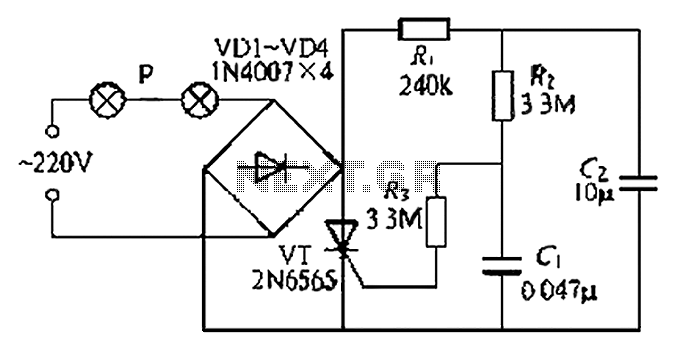
A simple and easy-to-implement one-way flashing lights string controller is designed for small shop or home decoration. This device utilizes a thyristor-based dimmer circuit, which operates effectively by managing large capacitance. The circuit includes a ten-microfarad capacitor connected to...

This approach utilizes a Hip-Hop, a shift register, and two gates (A). Before the one-shot pulse, the output of the NOR gate is 0. Consequently, the data input of the D-type flip-flop is equivalent to the trigger. When a...