
Quick On-Board Junction Tester

The use of a multimeter for detecting short circuits and broken tracks on printed circuit boards (PCBs) is a common practice among electronics engineers. The multimeter can effectively measure continuity and resistance, allowing for the identification of faulty connections. However, when it comes to evaluating the performance of active components such as transistors and diodes, the presence of the component on the PCB can lead to misleading readings. This is due to the interaction of other circuit elements that may influence the measurements.
To accurately test a transistor or diode, it is often necessary to desolder the component from the PCB. This process involves carefully removing the component while ensuring that the surrounding tracks are not damaged. Once the component is removed, the multimeter can be used to measure parameters such as current gain (hFE) for transistors or forward voltage drop for diodes without interference from other circuit elements.
Furthermore, the practical challenges of using a multimeter in this context include the need for precise probe placement. The probes must maintain contact with the component pins, which can be cumbersome, especially in densely populated PCBs. This requirement may lead to user fatigue, as the operator must hold the probes in place while simultaneously attempting to read the multimeter display. To mitigate these challenges, specialized testing fixtures or adapters can be utilized, allowing for hands-free operation and more accurate readings.
In summary, while multimeters are invaluable tools for diagnosing short circuits and broken tracks on PCBs, their effectiveness in testing active components is limited unless the components are removed from the circuit. Proper handling and testing techniques are essential to ensure accurate measurements and reliable circuit diagnostics.Short circuits or broken pcb tracks can be easily recognized by means of a Multimeter, but this tool can give wrong results when testing the efficiency of a transistor or diode, unless the device under test is unsoldered and removed from the pcb. A further shortcoming affecting such way of testing is the necessity to keep firmly the probes on the pins of the device under test and at the same time to turn the head continually to read the Multimeter display
🔗 External reference
Related Circuits
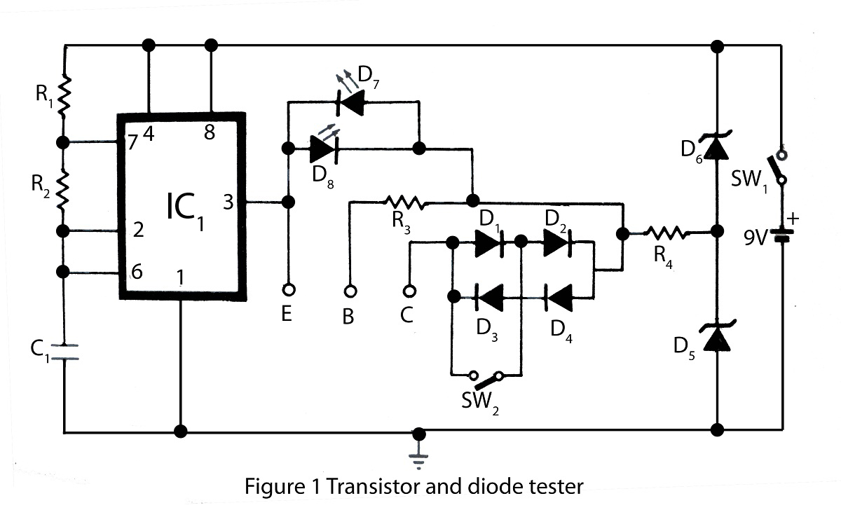
The transistor and diode tester available on this website is specifically designed for testing all types of transistors. Utilizing the principles of diode testing, it can also be used to check diodes. Various types of testing circuits can be...
This simple circuit utilizes a 741 operational amplifier (op-amp) in differential mode to function as a continuity tester. The voltage difference between the non-inverting and inverting inputs is amplified by the op-amp's full open-loop gain. Initially, if the resistors...
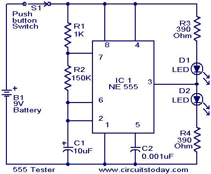
The NE555 timer is configured as an astable multivibrator. When the push button switch S1 is pressed, the LEDs D1 and D2 will flash alternately. When the output is high, D2 will illuminate, and when the output is low,...
A simple device designed for quickly checking common infrared remote controls can be beneficial for electronics enthusiasts who often need to repair or test these widespread devices. A reliable circuit was created using a few components: the LED will...
The Eico 666 is a capable tube tester whose functionality can be expanded with a modest investment of time to understand its schematic, operational regimes, and methods for adding new functionalities. This tester is known for supplying sufficient voltages...
The ADC Tester (A2100) is a LWDAQ device that records the output and power consumption of two ADCs. Its original purpose was comparative testing of two ADCs at different temperatures, but it has also proven to be an effective...