
Radiation Detector and Meter DT-590A/PDR-56F Scintillation Probe

The circuit described integrates multiple components to achieve high-voltage generation and precise signal processing for radiation detection. The JKL BXA-12579 inverter is critical in providing the necessary high voltage, while the rectification and filtering stages ensure a stable DC output for further processing. The use of Zener diodes for voltage regulation ensures that the delicate photomultiplier tube operates within its required parameters, enhancing the reliability of the detection system.
The signal processing section, utilizing a combination of transistors and NOR gates, allows for effective pulse discrimination and amplification. The design emphasizes the importance of timing and signal integrity, with careful consideration given to the interaction between the timing capacitor and the associated resistors. This ensures that the circuit can accurately respond to incoming radiation pulses, generating audible and visual feedback through the piezo speaker and potential output to other monitoring equipment.
The single-channel design of the probe, optimized for detecting specific gamma radiation, highlights the specialized nature of this application. Adjustments to the internal trimmers provide flexibility for calibration, ensuring that the probe can be fine-tuned for varying environmental conditions or specific detection requirements. This comprehensive approach to circuit design ensures effective radiation detection while maintaining user accessibility for adjustments and maintenance.This pdf file shows the schematic diagram of my home-built circuit to drive the PDR-56 probe. A JKL BXA-12579 inverter commonly used to drive cold-cathode fluorescent lamps is used as the high-voltage power supply. The BXA-12579 produces 1, 500 VACRMS for a 12 VDC input. The AC output is tapped straight from the transformer`s secondary and rectifie d by D1, a high-voltage diode rated at 20 kV and 0. 5 A. The rectified signal is filtered by C1, R1 and C2. -950 VDC for operation of the photomultiplier tube inside the PFR-56 probe are regulated by a series of Zener diodes (D2 D9). -9 V are generated by an isolated DKE 10A-05 DC/DC converter, and +3. 8 V are derived from the 12VDC input by a 3-pin 5 V linear regulator (U1) with its output voltage dropped by 2 series diodes (D11 and D12).
The signal input circuit is based directly on the military DT-590A/PDR-56 radiac meter as described in US Army Technical Manual TM 11-6665-245-34. In this part of the circuit, Q1, Q2 and Q3 form a discriminator and buffer-inverter circuit that determines the level of incoming pulses which are measured and provides a positive going pulse for use by U2.
Prior to any signal (positive pulse from the buffer inverter circuit Q3), the inputs to NOR gate U2A are both low, the output is high and transistor Q4 is conducting. A positive going pulse from Q3 starts the circuit into operation. When pin 1, U2A, goes high, its output goes low. The voltage change is coupled directly to the base of Q4 through timing capacitor C10. Q4 is then cut off and its collector goes high holding the output of U2A low. This condition holds until timing capacitor C10 discharges through resistor R10 enough to allow Q4 to turn on, causing pin 2 of U2A to revert to a low condition.
This action results in pin 3, U2A, first going low as the result of the inverter-buffer input pulse and then staying low until the timing capacitor discharges forming a negative going pulse on the inputs of U2B through U2D. Outputs from inverters U2B and U2C are tied together and connected to a piezo speaker to produce a click for each detection by the probe.
In addition, the output of U2D can be routed to a counter, small audio amplifier or other instrument. The circuit inside the probe is built as a single-channel counter, and is factory-tuned to detect only scintillation pulses from the Pu-239 gamma rays.
Thus, you shouldopen the single-channel window all the way tomake the probe sensitive to a much wider range of gamma energies. The following picture shows the trimmers inside the probe that need to be re-adjusted: 🔗 External reference
Related Circuits
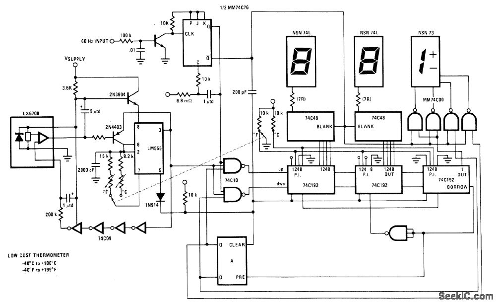
The National LX5700 temperature transducer supplies input to a code conversion circuit that drives a 3-digit LED display. This display indicates temperatures ranging from -40°F to +100°F or -40°F to +199°F, controlled by a ganged switch. The National LX5700...

The ESR Meter is essentially an AC Ohmmeter equipped with specialized scales and protective circuitry. It provides continuous readings of series resistance in electrolytic capacitors. Operating at 100 kHz, it maintains the capacitive reactance factor close to zero. The...
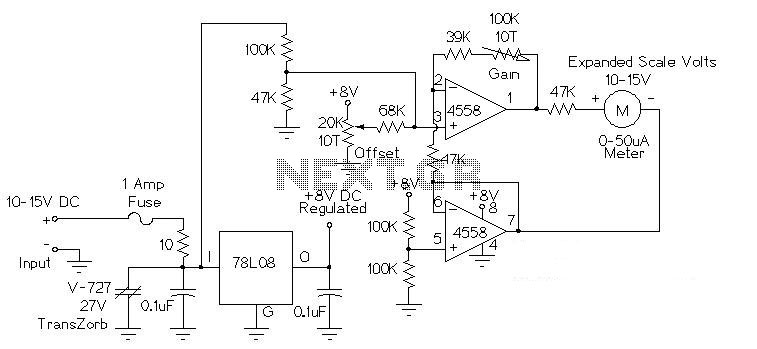
This circuit is used to measure the voltage on a 12V (nominal) lead acid rechargeable battery system. It was specifically designed for use in solar powered systems, but is general enough that it can be used for automotive or...
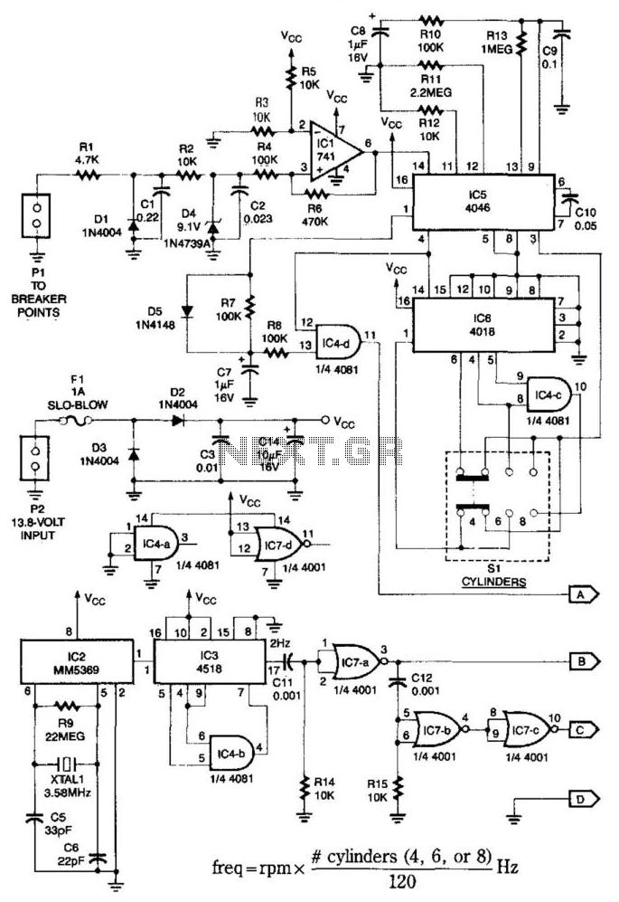
This system is compatible with 4-, 6-, or 8-cylinder automobiles. The timebase generated by IC5 functions as an oscillator that drives counter IC6, which divides the frequency by 6, 4, or 3 for 4-, 6-, or 8-cylinder engines, respectively....
The circuit was designed to create a low-cost frequency meter that will cover the range of 1 Hz to 1 MHz with a digital indication using three 7-segment displays. The frequency meter circuit operates by measuring the frequency of an...
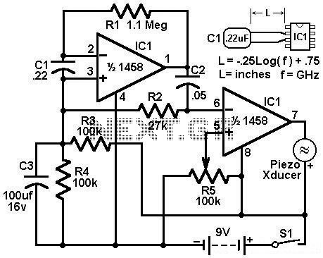
Economy radar detector circuit diagram. This circuit uses a 1458 dual op-amp to form a radar detector. C1 is the detector of the radar signal. The first op-amp forms a current-to-voltage converter, and the second op-amp buffers the output. The...