
Economy radar detector

The economy radar detector circuit is designed to detect radar signals effectively using a 1458 dual operational amplifier (op-amp) configuration. The circuit employs a capacitor, designated as C1, which acts as the radar signal detector. This capacitor is crucial for capturing the incoming radar signals and converting them into a usable electrical signal.
The first op-amp in the configuration is utilized as a current-to-voltage converter. This stage is essential for transforming the current output from C1 into a corresponding voltage signal, which can then be processed further. The op-amp's feedback mechanism ensures that the output voltage accurately reflects the radar signal's intensity, allowing for precise detection.
Following this, the second op-amp serves as a buffer for the output from the first stage. This buffering action is vital for isolating the signal and preventing any loading effects that might distort the output. By providing high input impedance and low output impedance, the buffer stage ensures that the signal maintains its integrity as it is sent to subsequent stages of processing or output devices.
The overall design of the economy radar detector circuit emphasizes simplicity and efficiency, making it suitable for applications that require basic radar detection without the complexity of more advanced systems. Proper implementation of this circuit can yield reliable performance in detecting radar signals, contributing to various electronic applications.Economy radar detector Circuit diagram This circuit uses a 1458 dual op-amp to form a radar detector. C1 is the detector of the radar signal. The first op-amp forms a current-to-voltage converter and the second op-amp buffers the output to.. 🔗 External reference
Related Circuits
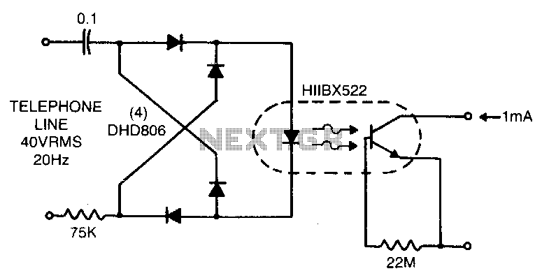
Low line current loading is provided by the H11BX522 photodarlington optocoupler, which delivers a 1 mA output from a 0.5 mA input. The H11BX522 is a photodarlington optocoupler that is designed to provide electrical isolation between its input and output...
Here's a circuit that takes advantage of the photo-voltaic voltage of an ordinary LED. The LED voltage is buffered by a junction FET transistor and then applied to the inverting input of an op-amp with a gain of about...
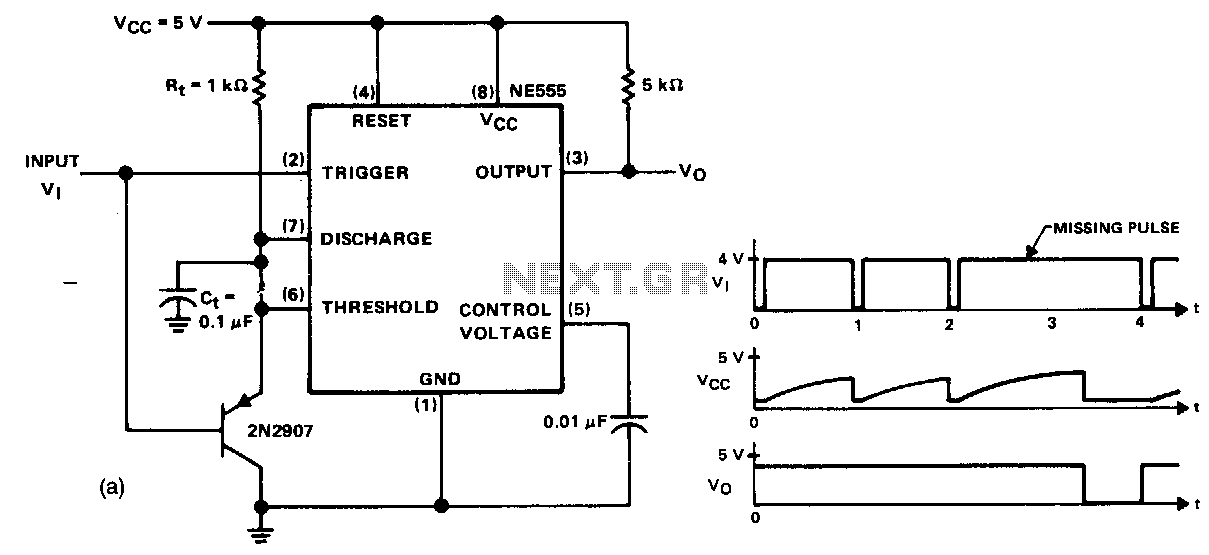
This circuit detects a missing pulse or an abnormally long interval between consecutive pulses in a pulse train. The timer is configured in monostable mode, with the time delay set slightly longer than the duration of the input pulses....
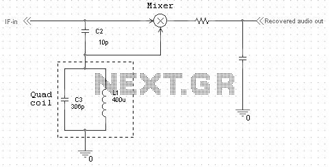
Quadrature FM detectors use a high-reactance capacitor (C2) to produce two signals with a 90 degree phase difference. The phase-shifted signal is then applied to an LC-tuned resonant at the carrier frequency (L1 and C3). Frequency changes will then...
This is a very basic infrared detector/emitter circuit. One major downside of this circuit, is that ambient infrared light will interfere with its detecting obstacles. The described circuit functions as a basic infrared (IR) detector and emitter system, commonly utilized...

This circuit separates an input voltage signal into its components: (1) the absolute value and (2) the polarity or 'sign' (+ or -). It is designed to handle direct current (DC) signals. The circuit operates by utilizing operational amplifiers (op-amps)...