
Audio Controlled Christmas Lights

The circuit design involves integrating an audio signal from an amplified computer speaker to control the flashing of Christmas lights in sync with the music. The primary components include a diode bridge, which serves to rectify the AC signal output from the speaker, converting it into a pulsating DC signal. This rectified signal is then used to control the operation of a CRYDOM solid-state relay (SSR), which is responsible for switching the Christmas lights on and off.
The diode bridge consists of four diodes arranged in a configuration that allows current to flow in both directions, thus ensuring that the output remains positive regardless of the input signal's polarity. This is essential for providing a stable control signal to the SSR. The CRYDOM SSR is chosen for its ability to handle high currents and voltages, making it suitable for powering multiple strings of lights without the risk of mechanical failure associated with traditional relays.
To enhance the performance of the circuit, a capacitor can be added across the output of the diode bridge. This capacitor acts as a filter, smoothing out the pulsating DC signal and providing a more consistent voltage level to the SSR. The value of the capacitor should be chosen based on the desired response time for the lights, allowing them to remain illuminated for a longer duration with each beat of the music.
In conclusion, this circuit effectively combines audio signal processing with lighting control, creating a visually appealing synchronization of lights flashing in rhythm with music. Proper consideration of component ratings and circuit design will ensure reliable operation and safety during use.The basic Idea was to have Christmas lights flash with the music. In my design I use an ordinary amplified computer speaker, a diode bridge, and a ‘CRYDOM’ SSR (Solid State Relay). In order to increase the time that the lights were on as well as protect the SSR I used a Diode Bridge to rectify the signal from the amplifier circuit.”
🔗 External reference
Related Circuits
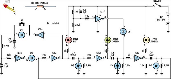
This toy traffic signal utilizes a single low-cost hex Schmitt-trigger inverter IC (IC1a-IC1f) to directly control three colored LEDs (red, green, and amber). Upon activation, the circuit illuminates the red signal for 30 seconds, followed by green for 6...
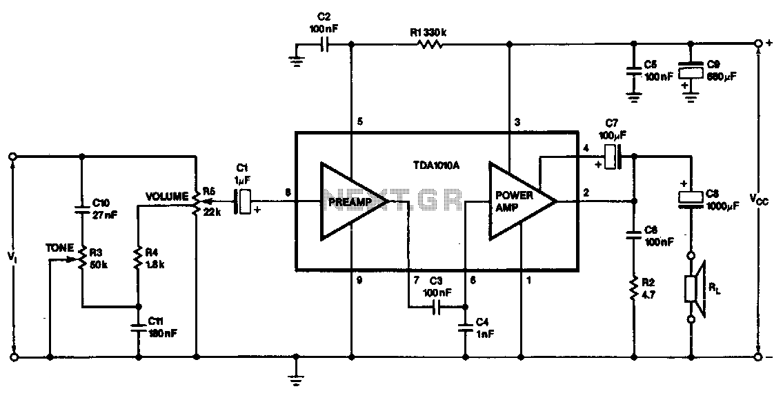
This monolithic IC, class-B audio amplifier circuit is a 6-W car radio amplifier for use with 4-ohm and 2-ohm load impedances. The monolithic integrated circuit (IC) described is designed to function as a Class-B audio amplifier, specifically tailored for...

The FM transmitter is relatively simple to build and requires only one adjustment, making it ideal for beginners. It is important to clarify that, with wide-band deviation, the Voltage Controlled Oscillator (VCO) is never locked in phase, only in...

Utilizing an analog audio line delay, it is possible to virtually adjust the size of a room. By simply turning a knob on the audio equipment, one can modify the perceived room size. The circuit described herein facilitates this...
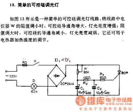
A simple silicon-controlled rectifier (SCR) dimmer circuit is depicted in Figure 13. This circuit is designed to control the brightness of lights. As the resistance in the potentiometer decreases, the conduction angle of the SCR increases, resulting in an...
This circuit is designed to drive a low-power speaker using a sound effects module or a noise generator. It can also be utilized to create amplified speakers for computer use. The circuit amplifies the input signal by a factor...