
Radio harmonic detection circuit

The described circuit primarily focuses on the demodulation of amplitude-modulated signals. The initial stage involves amplifying the intermediate frequency (IF) signal, which is crucial for enhancing the signal-to-noise ratio before demodulation. The two-stage detection process utilizes a diode (referred to as Dr) to rectify the IF signal, allowing the extraction of the audio information.
In the first stage of detection, the diode conducts during the positive half-cycle of the IF signal, allowing the audio envelope to pass while blocking the negative half-cycle. This results in a pulsating DC signal that corresponds to the audio waveform. The second stage further refines this signal, typically involving additional filtering to smooth out the rectified waveform and eliminate high-frequency components that are not part of the audio signal.
After the demodulation and detection process, the resulting audio signal is forwarded to a power amplifier stage. This stage is responsible for boosting the audio signal's power level to drive speakers or other audio output devices effectively. The overall design ensures that the audio output maintains fidelity to the original modulated signal while providing sufficient power for practical applications.
For testing and debugging purposes, the circuit's performance can be monitored using a multimeter to measure voltage levels and an oscilloscope to visualize the waveforms at various points in the circuit. This allows engineers to verify the integrity of the demodulation process and make necessary adjustments for optimal performance.FIG demodulation and detection circuit is a radio, AM intermediate frequency signal IF amplifier after a two-stage detection performed by the diode Dr, the audio signal from th e IF carrier detection, and then sending the subsequent stage of the power amplifier. Demodulation and detection of the waveform can be shown with a multimeter and wave vase debugging and testing
Related Circuits
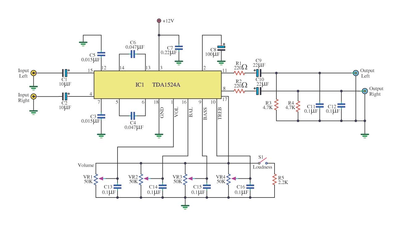
This is a simple tone control circuit using the TDA1524A, which is a key component in this IC chip diagram from Philips. The circuit allows for tone control adjustments such as bass, treble, and balance, enabling users to fine-tune...
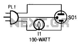
The tester provides an audible indication of the logic level of the signal presented to its input. A logic high is indicated by a high tone, a logic low is indicated by a low tone, and oscillation is indicated...
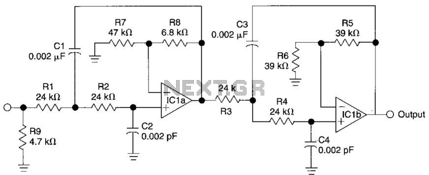
This circuit is a fourth-order low-pass filter designed for operation at kilohertz frequencies. The component values for resistors R1, R2, and capacitors C1, C2, as well as resistors R3, R4 and capacitors C3, C4 can be adjusted for functionality...
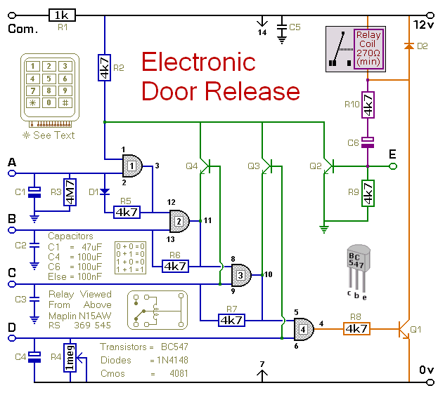
This circuit is designed to operate an electrical door-release mechanism, but it can also be utilized for other applications. When the user enters a four-digit code of their choice, the relay will energize for a preset time period. The...
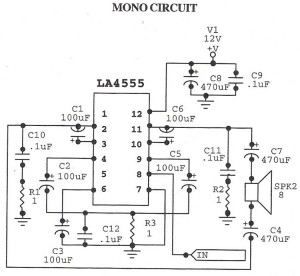
The following circuit illustrates an audio amplifier mono circuit diagram. This circuit is based on the LA4555 integrated circuit (IC). Features include a mono configuration and a power output of 2.3 watts. The audio amplifier circuit utilizing the LA4555 IC...
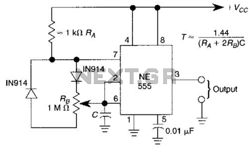
A 1.2-kHz oscillator utilizing a potentiometer and steering diodes allows for a duty cycle adjustment ranging from 1% to 99%. The frequency can be altered by varying the capacitor CI. It is important to note that the diodes may...