
Radio Motor Controller Schematic

The radio control circuit operates on a 27.9 MHz frequency, which is suitable for short-range communication. The transmitter unit typically includes an oscillator circuit that generates a high-frequency signal, modulated with the control commands. This modulation can be achieved using various techniques, such as amplitude modulation (AM) or frequency modulation (FM), depending on the design requirements.
The design of the transmitter may incorporate push buttons or a joystick, which serve as input devices. When a button is pressed or the joystick is moved, the corresponding electrical pulse is generated. This pulse sequence is then encoded into a format suitable for transmission. The use of a microcontroller or a dedicated encoding IC can facilitate this process, ensuring accurate command representation.
The active antenna in the transmitter is crucial for effectively radiating the modulated signal. The antenna design can vary, but it typically consists of a simple wire element tuned to the operating frequency. It is essential for maximizing transmission range and minimizing signal loss.
On the receiving end, the radio receiver consists of a tuned circuit that filters out signals at the 27.9 MHz frequency. The receiver's sensitivity is vital, as it must detect weak signals that may be affected by environmental factors. Once the signal is captured, a demodulation process occurs, converting the received radio waves back into electrical pulses. The decoding circuit analyzes the pulse sequence to determine the appropriate command.
The motor control section of the circuit typically employs a motor driver IC or a transistor-based H-bridge configuration to control the direction and speed of the motors. The application of voltage to the motors is managed based on the decoded commands, allowing for precise control over the vehicle's movement.
In summary, this radio control circuit provides a versatile solution for operating small motors with remote commands, utilizing a straightforward architecture that combines radio frequency communication, pulse encoding, and motor control techniques. The use of the AF2310 integrated circuit streamlines the design, providing a reliable foundation for both the transmitter and receiver components.A very nice radio control circuit can be used to control the circuit shown below in small motors. The circuit is very similar to the car radio remote control toy 7 function: fo rward, forward, left, right, forward, backward, left behind, behind the right and stop. You can also use some other need a few simple lines, electronic motor controller circuits, RF circuits. Remote control operation requires a frequency of 27.9 megahertz 9 volt power supply of the radio motor controller circuit consists of two parts of a radio transmitter and a radio receiver.
For remote control you can use some contact with push buttons or a miniature joystick control. Command is coded sequence of electrical pulses used by different sets of electrical contacts; the number of pulses depends on the command being sent. 27.9 MHz frequency tuning circuit creates a pulse signal sent to the active antenna. Antenna radio energy into electrical energy, creating a radio burst of energy, through the air and picked up the receiver and radio in the car can be understood flow.
Car antennas collecting radio energy and convert it into electricity, if the car is open, then the radio receiver in the cars electrical energy continuously monitoring its antenna. The receiver is a filter, which is about 27.9 MHz and adjust the zoom block energy antennas pick up any energy from outside the region.
If the remote control sends a command, then it will pick up the signal from the radio receiver and converted back to the original pulse sequence. Decoding circuit, and then decide whether the received pulse sequence by measuring the number of commands sent.
Run signal is sent to the motor. When operating with a strong battery, within the scope of an open area at least 40 feet barriers will reduce the ability of radio signals travel through the air and reduce operating range, but will not stop it completely. In the car, weak batteries will reduce power motors and reduce the ability of the receiver from the transmitter, filters, amplifies, and decodes the command.
When receiving the command to turn left or right, the steering motor applied voltage, since the steering wheel is connected to the bar, the car will open. Turn the other direction, the motor voltage is reversed. Steering motor drives the same electrical engineering. When forward voltage is applied to the drive motor receives a command, the voltage is reversed backwards.
Both the receiver and transmitter AF2310 integrated circuit basis.
Related Circuits
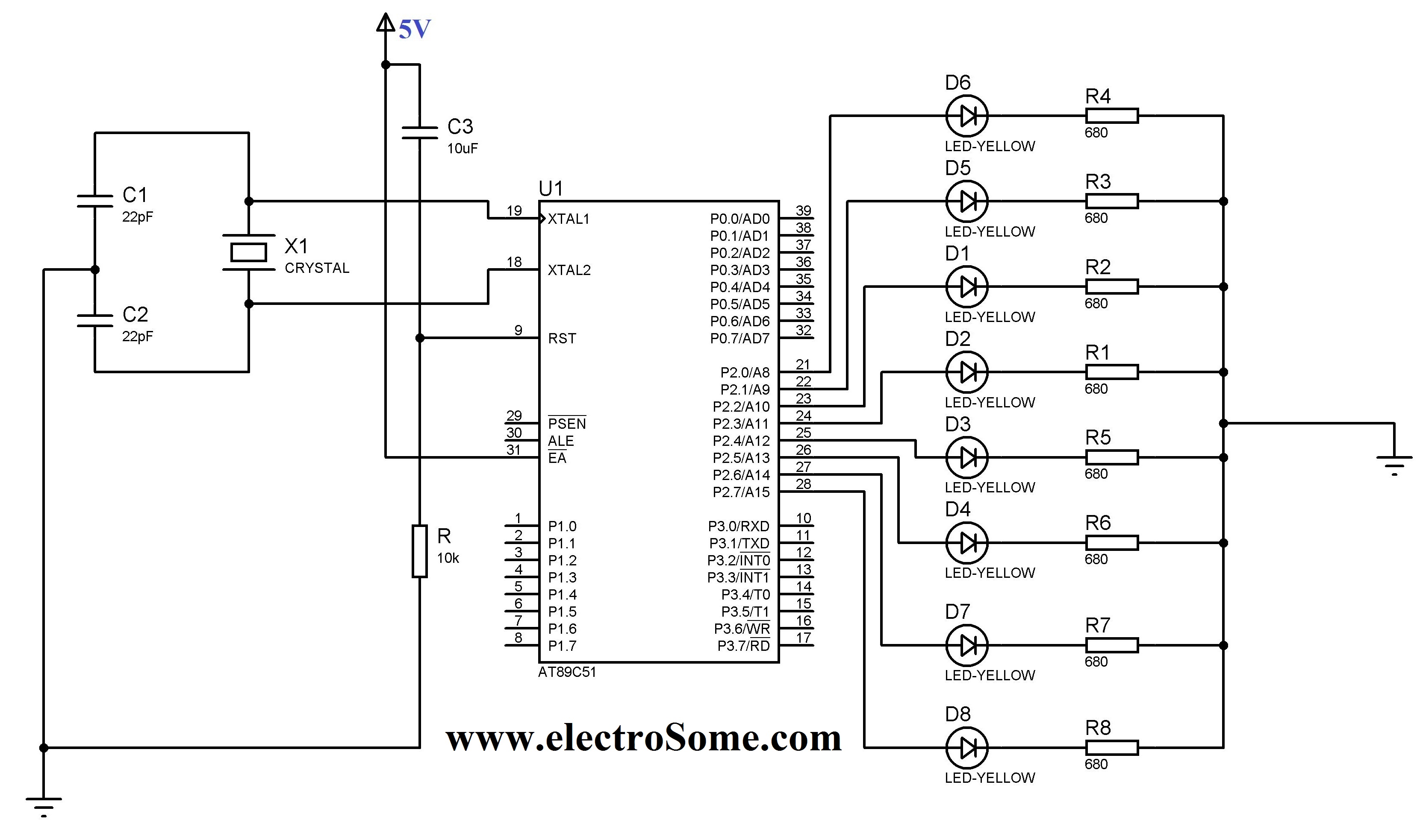
The 8051 controller is mask-programmable, meaning it is programmed during manufacturing and cannot be reprogrammed afterward. However, the AT89C51 microcontroller, a derivative of the 8051, is reprogrammable. This device includes a timer, a serial port interface, and interrupt control,...
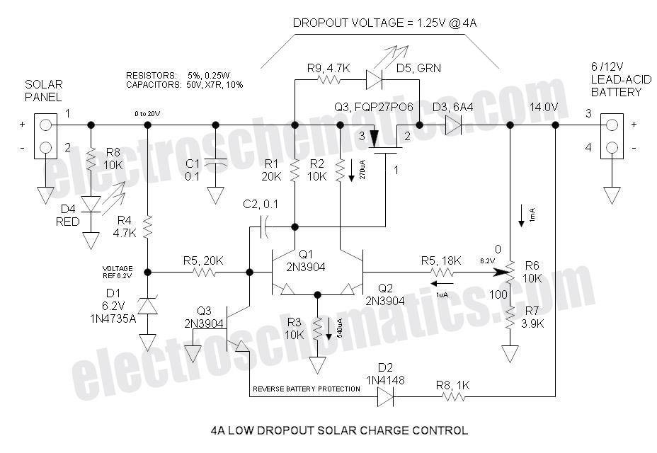
This Low Dropout Voltage (LDO) solar charge controller employs a differential amplifier and a series P-channel MOSFET linear regulator, which work exceptionally well together. The output voltage is adjustable and primarily designed for charging 12V lead-acid batteries. The input...
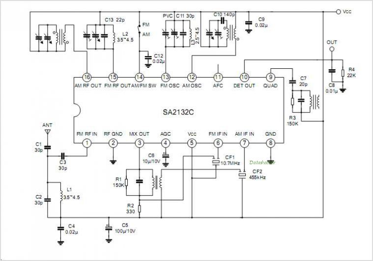
The SA605 is a high-performance monolithic low-power FM intermediate frequency (IF) system that integrates a mixer, oscillator, two limiting intermediate frequency amplifiers, a quadrature detector, muting, a logarithmic received signal strength indicator (RSSI), and a voltage regulator. It combines...
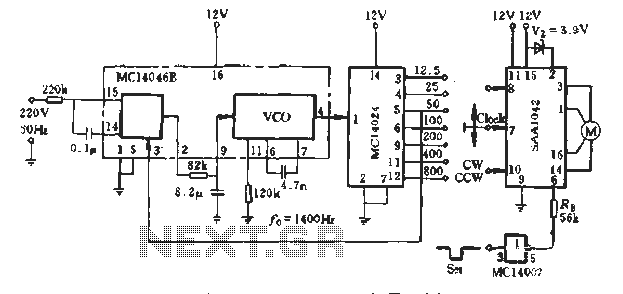
A typical application example is presented, demonstrating the SAA1042 12V stepper motor drive configuration. The phase winding current is set at 200mA. According to RB Figure 5-10, a resistor value of RE = 56kΩ is selected. This resistor is...
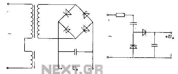
The pre-regulator circuit is connected to a capacitor and a resistor element. The regulator operates in its conducting direction through the input. A capacitor is connected to AC power, and in the blocking direction, it limits the current, allowing...
Many radio amateurs are interested in powering simple radio receivers using "free energy," which refers to energy obtained directly from the air via the receiver antenna. The circuits described can facilitate radio reception through a loudspeaker. However, questions remain...