
Zero rectifier regulator schematic

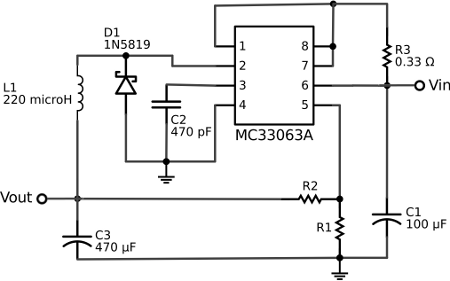
The described pre-regulator circuit serves as an essential component in power supply applications, where it plays a critical role in managing voltage levels and ensuring stability in the output. The circuit typically consists of a capacitor, a resistor, and a voltage regulator. The capacitor is connected to the AC power source, which allows it to store energy and smooth out fluctuations in voltage.
In this configuration, the capacitor acts as a filter, charging when the AC voltage exceeds a certain threshold and discharging when the voltage drops, thereby providing a more stable DC output. The resistor element is integrated to limit the current flow, preventing excessive charging of the capacitor and ensuring that the system operates within safe parameters.
The regulator within the circuit is designed to maintain a consistent output voltage despite variations in the input voltage or load conditions. It achieves this by conducting current in one direction, effectively controlling the voltage delivered to the load. This regulation is crucial for sensitive electronic devices that require a stable power supply for optimal performance.
The bridge rectifier circuit, while effective in converting AC to DC, can introduce a significant voltage ripple in the output. However, the direct connection to the AC power supply minimizes current consumption, making the circuit efficient in terms of energy usage. The design must consider the trade-off between ripple voltage and power efficiency, as high ripple can affect the performance of downstream components.
In summary, this pre-regulator circuit is vital for applications requiring stable voltage levels, utilizing a capacitor for energy storage and current limiting, alongside a regulator to ensure consistent output. Proper design and component selection are essential to optimize performance and reliability in various electronic systems.The pre-regulator circuit connected to the capacitor, resistor element. Regulator in its conducting direction through the input capacitor connected to AC power, and in the blocking direction to limit the current, so that the capacitor recharge followed, so that the output voltage stability. The bridge circuit voltage ripple relatively large, but due to the direct connection to AC power, it consumes less current.
Related Circuits
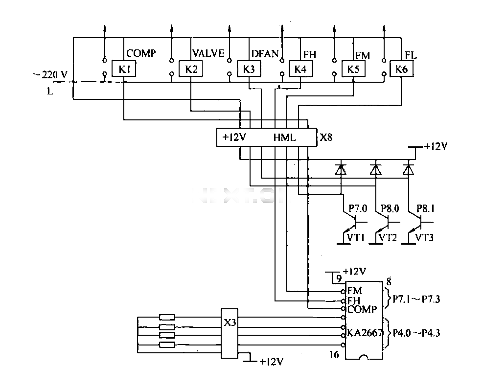
The driving circuit depicted in Figure 18-12 consists of a connection between the driving portion, the microcontroller, and the air conditioning operation components of the bridge. The microcontroller's digital signal levels from ports P4.0 to P4.3 (approximately 12 feet)...
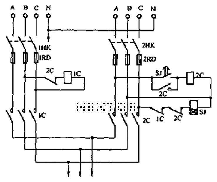
A dual three-phase power line circuit is illustrated in the figure. When the knife switches 1HK and 2HK are closed simultaneously, the normally closed contact 1C disconnects the power supply to the time relay SJ, allowing power to reach...
The voltage regulator integrated into the Arduino Uno is a linear-type regulator, which exhibits poor efficiency. When operating the ATmega238 at 5V with a 9V battery, nearly half of the battery's energy is wasted as heat by the regulator....
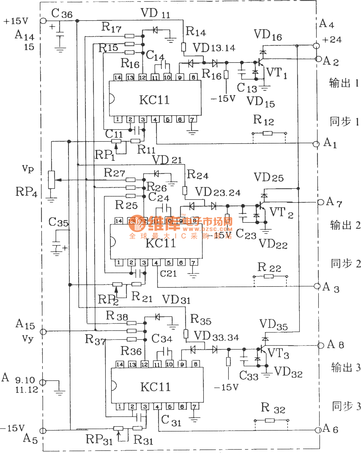
The KCZ3 is an integrated three-pulse triggering component designed for use in three-phase half-bridge inverters. Each phase output pulse can reliably drive a high-power thyristor and is adaptable to various phase voltages. The electrical parameters are as follows: Phase...

The LA9472A is a 2A monolithic step down switching regulator operating in continuous mode and realized in a new BCD technology allowing the integration of isolated, vertical DMOS power transistors with mixed CMOS/bipolar transistors. The device can deliver 2A...
A detailed DIY remote-controlled AC fan regulator with 10-stage speed control. It is built using the ATmega8 microcontroller, and includes full source code and PCB layout. This project involves designing a remote-controlled AC fan regulator that allows users to adjust...