
Based LMD18245 bipolar stepper motor control circuit diagram

The LMD18245 integrated circuit is designed to efficiently manage motor control applications by utilizing advanced techniques to minimize power loss and optimize performance. The implementation of a fixed off-time chopper strategy allows for precise control of the motor current, ensuring that the motor operates within its specified parameters. The choice of a 20 kΩ resistor in conjunction with a 2.2 nF capacitor is critical for establishing the timing characteristics of the chopper operation, directly influencing the off-time duration and, consequently, the motor's performance.
The capability of the LMD18245 to support both DC brush motors and bipolar stepper motors broadens its application range, making it suitable for various automation and robotics projects. The integration of a DMOS H-bridge power stage not only enhances the output current capacity but also improves thermal management, as the low RDS(ON) reduces power dissipation during operation.
Furthermore, the internal body diode of the DMOS structure simplifies the design by removing the need for additional discrete components, which can complicate the circuit layout and increase the overall size of the motor driver. The digital control aspect, facilitated by the 4-digit DAC, allows for seamless integration with microcontrollers or digital signal processors, enabling sophisticated control algorithms that can adapt to different operational modes such as full step, half step, and micro-stepping.
In conclusion, the LMD18245 bipolar chopper drive stepper motor power stage represents a significant advancement in motor control technology, combining efficiency, flexibility, and ease of use in a compact solution suitable for a broad range of applications.An innovative current detection method, eliminating the power loss of the sense resistor in series with the motor, a 4-digit - analog converter (DAC), provides a digital contro l motor current path, and, by extension, to simplify the implementation of full, half and micro step motor driver, which LMD18245 the application circuit is a bipolar chopper drive stepper motor power stage. 20k resistor and 2.2 nF capacitor connected between the RC and set off time of about 48 microseconds, 20k resistor connected to the output and ground about 200 milliamperes per volt threshold is set to gain in the chopper CS.
Use LMD18245 full-bridge power amplifier integrated DC brush motor bipolar stepper motor or a stage, all of the circuit can be designed to block the application of a variety of motor control and current drive needed. LMD18245 motor control current through a fixed off-time chopper technique, all DMOS H-bridge power stage delivers up to 3A of continuous output current (6A peak) at supply voltages up to 55V DMOS power switch is an efficient low RDS ( ON), and a diode internal DMOS body structure, eliminating the typically required discrete diode clamp bipolar power stage.
An innovative current detection method, eliminating the power loss of the sense resistor in series with the motor, a 4-digit - analog converter (DAC), provides a digital control motor current path, and, by extension, to simplify the implementation of full, half and micro step motor driver application circuit LMD18245 this is a bipolar chopper drive stepper motor power stage. 20k resistor and 2.2 nF capacitor connected between the RC and set off time of about 48 microseconds, 20k resistor connected to the output and ground about 200 milliamperes per volt threshold is set to gain in the chopper CS.
Direction for digital signal control chopped threshold, winding current, by extension, drive type (full step, half step, and so on). Or a digital processor controller usually provide control signals.
Related Circuits
These two projects, Wah and Fuzz, are the results of a modification to a Morley dual channel volume control pedal that one of my sons suggested I undertake as he had no use for the volume unit but thought...
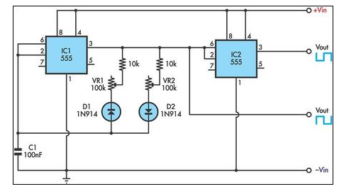
This circuit allows for the independent variation of the on/off times of a 555 timer across a wide range. This capability is not achievable with a conventional 555 timer circuit. The described circuit enhances the functionality of the standard 555...
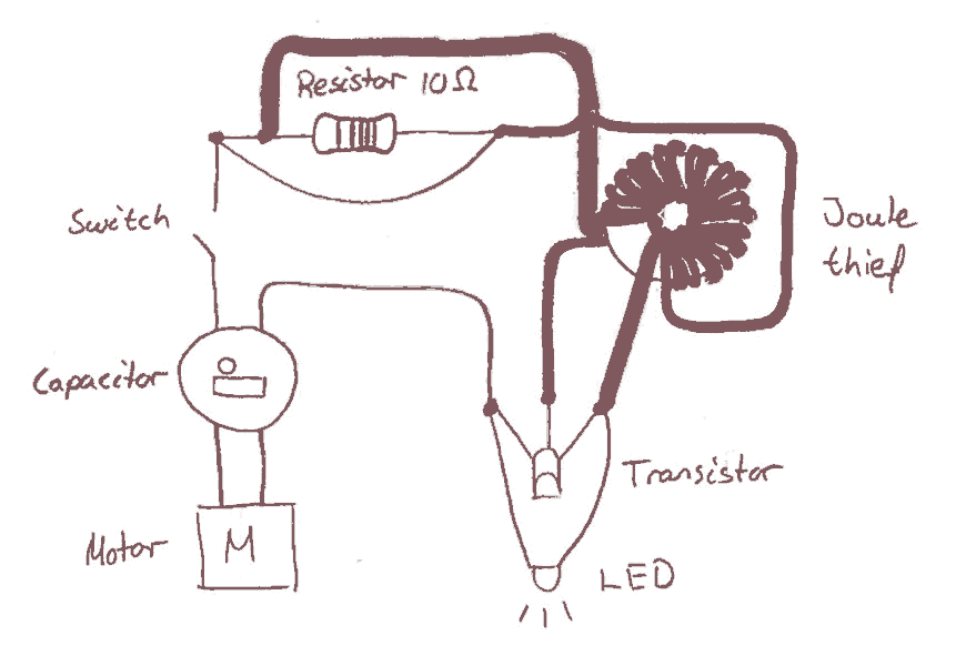
Early in the electronics design process, the decision was made to implement a joule saver in the circuit. The intention of using a joule saver is to maintain the LED light illumination even after the handle is no longer...
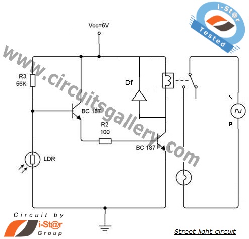
An automatic street light system is increasingly common, providing an intelligent mechanism for street lighting. It automatically illuminates during the night and utilizes incandescent lamps instead of LEDs for energy savings. This document outlines the process of constructing an...
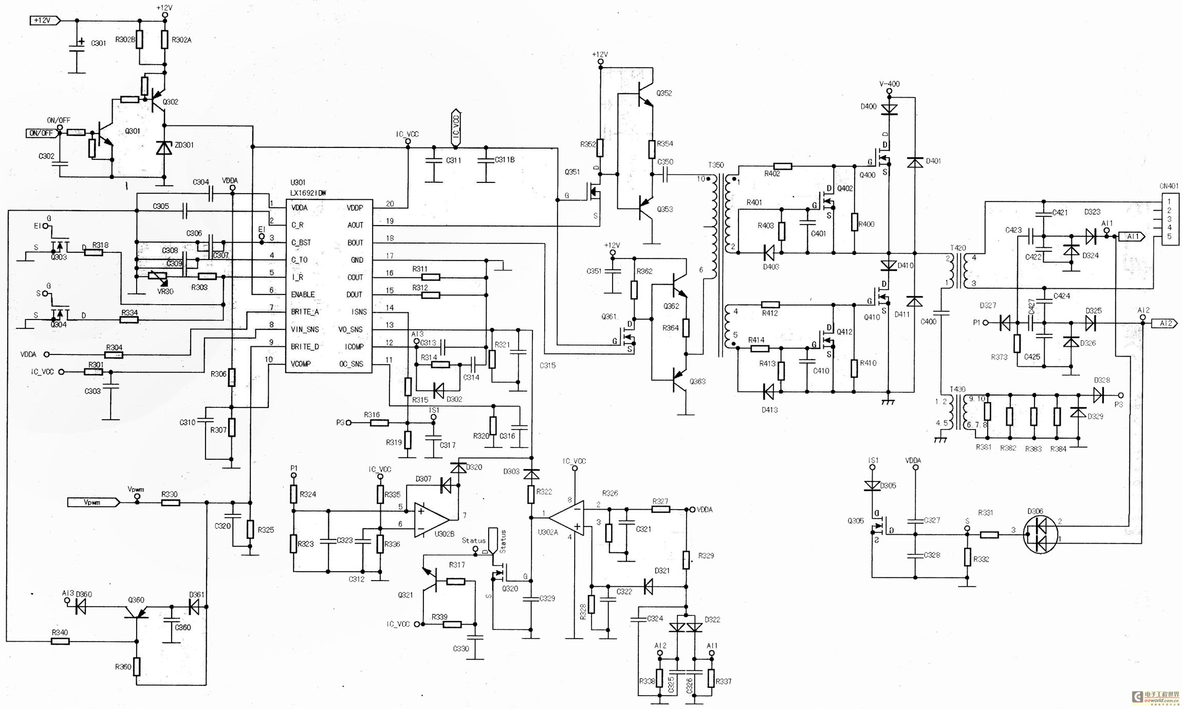
The main component is the LG26 one-inch screens integrated with the FSP107-2PS01 two-in-one electrical power package, which utilizes a direct drive CCFL modulator tube. This setup is compatible with screens from other manufacturers, such as Samsung and AU, but...
A high voltage power supply DC converter that operates between 3V to 500V has been suggested for use with Geiger tubes. However, during simulation, the output remained at nearly 9V, which matches the input voltage. The schematic drawn has...