
monitor an input pulse train

The missing pulse detector circuit is primarily based on the 555 timer IC configured in a monostable mode. In this configuration, the 555 timer generates a single output pulse when triggered by an input signal. The circuit continuously monitors the input pulse train from the IR sensor, which is activated by the remote control. The IR sensor outputs a series of pulses as long as the IR beam is uninterrupted.
When the IR beam is obstructed, indicating a missed pulse, the 555 timer's output transitions from a high state to a low state. This transition serves as a notification to the Basic Stamp microcontroller, which can then execute a predetermined response based on the missing pulse event. The circuit's design includes a resistor (R2) that must be calibrated to account for variations in the remote control buttons, ensuring reliable detection of pulse interruptions.
Incorporating additional components such as capacitors may enhance the circuit's stability and response time. The specific values of the resistors and capacitors can be calculated based on the desired timing characteristics of the pulse detection. Additionally, a diode may be included to protect the circuit from reverse polarity or voltage spikes that could occur from the IR sensor's output.
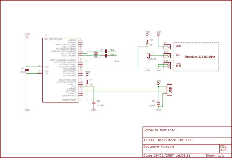
Overall, the missing pulse detector is a valuable component for applications requiring real-time monitoring of pulse signals, allowing for responsive actions when interruptions occur. This circuit exemplifies the integration of traditional electronic components in modern applications, showcasing the versatility and functionality of the 555 timer IC in pulse detection scenarios.This circuit is a missing pulse detector. It is used in the_ General Purpose Controller Board with Basic Stamp 1. This circuit is used to monitor an input pulse train, and when a pulse is missed the 555 timer output will switch low. For the General Purpose Controller Board the input pulses are provided from an IR sensor salvaged from an old VCR.
A n "All In One Remote" is used to trigger the IR sensor continuously by clamping one of the remote buttons down, which causes the remote to transmit continuously. When the IR beam is broken by someone walking past it the missing pulse circuit produces an output to the Basic Stamp.
R2 must be adjusted differently for different buttons on the remote. 🔗 External reference
Related Circuits
This thread explains the creation of a custom USB tire pressure monitoring system by modifying an aftermarket kit purchased on eBay. The initial step involved... The project entails the design and implementation of a USB tire pressure monitoring system (TPMS)...

Unique applications of the 567 tone/frequency decoder IC include its use as a pulse generator with a 25% duty cycle. This signal generator produces... The 567 tone/frequency decoder IC is a versatile component widely used in various electronic applications, particularly...
A rectangular-wave pulse generator with an extremely long period can be constructed using only two components: a National Semiconductor LM3710 supervisor integrated circuit (IC) and a 100-nF capacitor to suppress noise spikes. This circuit leverages the watchdog and reset...

This circuit uses a 74HCT74, 74HCT00, and a LM311 to form a frequency comparator. The two pulse trains are fed to two D-type flip-flops (triggered by the leading edges). The flip-flops' outputs are compared in a NAND gate. If...

This heatsink temperature monitor circuit uses three LEDs to signal when the temperature exceeds two boundary levels. When the heatsink temperature is below 50-60°C (122-140°F), the green LED lights up. The yellow LED indicates that the temperature is between...

The circuit below demonstrates the generation of a single positive pulse that is delayed in relation to the trigger input time. It is similar to a previously described circuit but utilizes two stages, allowing for control over both the...