
2012 HONDA ODYSSEY RADIO WIRING DIAGRAM

The 2012 Honda Odyssey Radio Wiring Diagram Manual provides a detailed schematic of the audio system's wiring configuration for the vehicle. This manual is essential for understanding the connections and functionalities of the radio unit, speakers, and associated components within the vehicle's audio system.
The wiring diagram typically includes color-coded wires that indicate their specific functions, such as power supply, ground, speaker outputs, and antenna connections. For instance, the power wire is often represented in red, while the ground wire may be shown in black. The diagram also illustrates the pin configuration for the radio harness connector, ensuring correct installation and troubleshooting.
In addition to the wiring details, the manual may offer insights into the integration of additional audio components, such as amplifiers or subwoofers, and how they can be connected to the existing system. It is crucial for technicians and DIY enthusiasts to refer to this manual to avoid miswiring, which can lead to malfunctioning audio systems or electrical issues within the vehicle.
Overall, the 2012 Honda Odyssey Radio Wiring Diagram Manual is an indispensable resource for anyone looking to install, repair, or modify the audio system in this vehicle model.2012 Honda Odyssey Radio Wiring Diagram Manual PDF Download. 🔗 External reference
Related Circuits
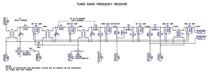
Tuned radio frequency receiver. A radio receiver consisting of several amplifier stages that... A tuned radio frequency (TRF) receiver is a type of radio receiver that utilizes multiple amplification stages to enhance the reception of radio frequency signals. The design...
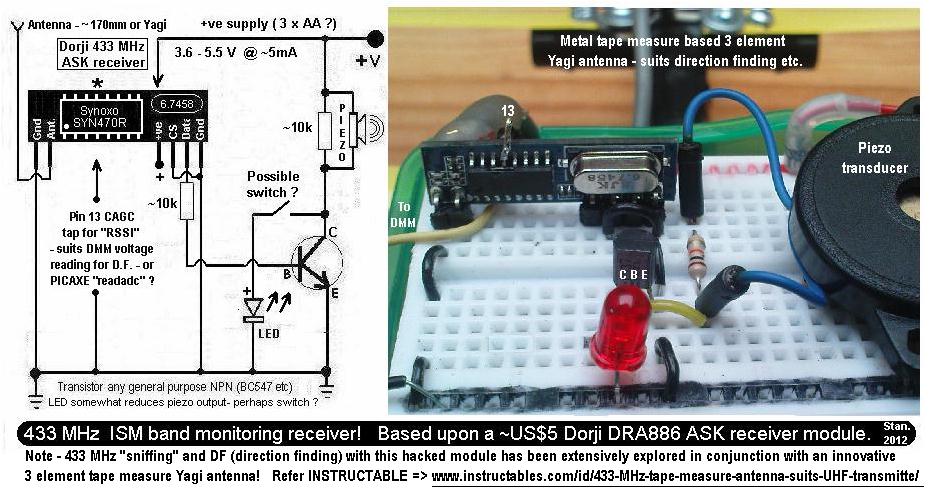
This is a simple 433.92 MHz short-range radio beacon that can be useful for locating downed R/C planes, lost balloons, model rockets, or possibly hidden items. The 433.92 MHz short-range radio beacon circuit is designed to transmit a signal over...
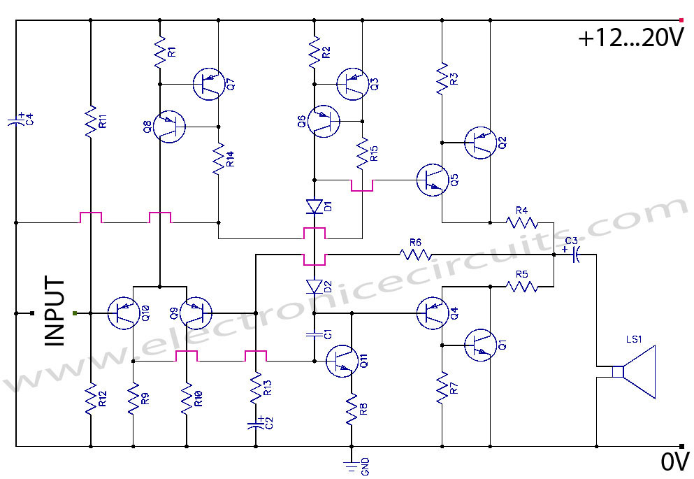
Discrete Class AB Transistor Audio Power Amplifier Circuit Diagram. This is a Class AB transistor power amplifier. It is a simple amplifier to... A Class AB transistor audio power amplifier is designed to provide high-quality amplification for audio signals while...
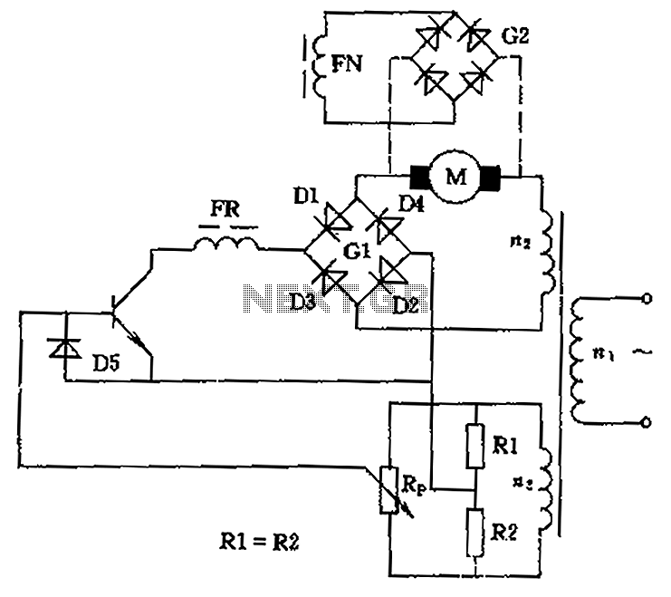
The circuit is designed to control the speed and direction of low-power DC motors, including series and shunt motors. It utilizes a rectifier bridge (G1) connected in series with the motor and linked to the secondary winding (n2) of...

The add-on circuit presented here is useful for stereo systems. This circuit has provisions for connecting stereo outputs from four different sources or channels as inputs, with only one of them selected and connected to the output at any...
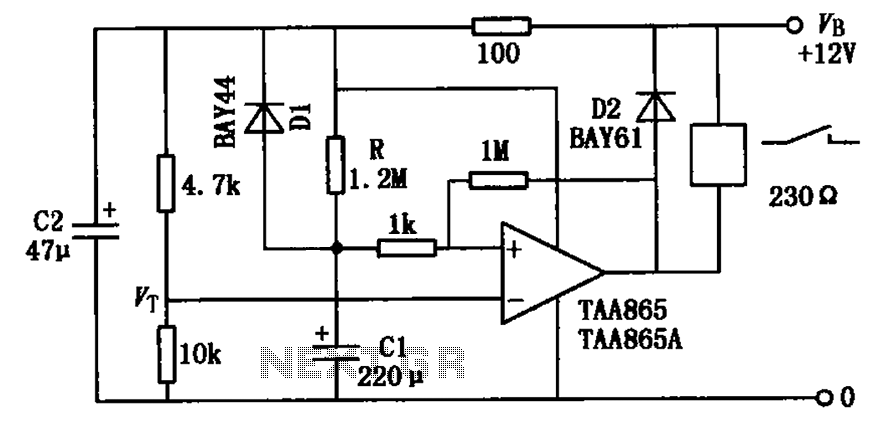
The circuit illustrated in the figure is a delayed release operational amplifier relay circuit. When the power switch is activated, a resistor of 4.7k is connected to the inverting input terminal of the operational amplifier. Additionally, a 10k resistor...