
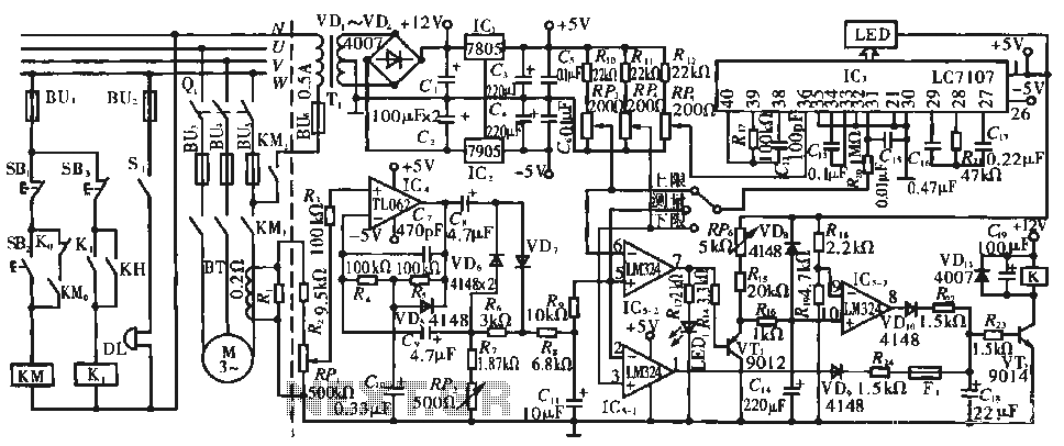
Forward and reverse running short brake circuit

The KM3 braking contactor circuit is designed to provide effective braking control in three-phase motor applications. The contactor operates by utilizing its normally open contacts, which remain open during normal operation. When a shutdown signal is received, the contactor is energized, causing the contacts to close. This closure effectively shorts the three-phase stator windings of the motor.
The shorting of the stator windings results in a rapid decrease in the motor's rotational speed, allowing for efficient braking. The circuit ensures that the motor comes to a stop quickly and safely, which is crucial in applications where immediate stopping is necessary to prevent accidents or equipment damage.
In addition, the design of the KM3 contactor includes features to handle the electrical load and ensure reliability during operation. The contactor is rated for the specific voltage and current levels associated with the motor it controls. Proper selection of the contactor, along with appropriate protective devices such as fuses or circuit breakers, is essential to safeguard the circuit from overload conditions.
Overall, the circuit provides a straightforward yet effective means of integrating braking functionality into three-phase motor systems, enhancing operational safety and performance. Circuit shown in Figure 3-154. Figure, KM3 braking contactors. Shutdown, you can disconnect the os. At this time, KM3 was electric pull its normally open contact closure shorti ng the three-phase stator windings to achieve the purpose of the brake.
Related Circuits
The circuit operates during standard inspection work by utilizing the voltage across resistor R2, which is connected to RP, to generate the input signal for IC4. Components R3 through Rg, along with capacitors C7 and C1, and diodes VD7...
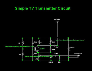
Many individuals inquire about TV transmitters. This document provides a useful circuit diagram that enables signal transmission over distances of 75 to 100 meters. The circuit diagram is not original but was provided by a colleague. Contributions of circuit...
Undervoltage release operates over an extended period. When the power supply voltage drops within the operating voltage range, it triggers the release mechanism, resulting in the rotation of the tripping axle and the disconnection of the circuit breaker. There...
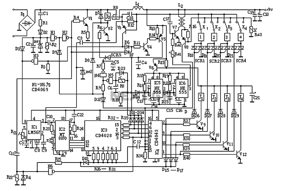
The circuit operates by sending ringing pulses through capacitor C1, resistor R1, and diode D2 to charge capacitor C2 to a voltage of 6V. This voltage causes transistors N1 and N2 to reverse, which activates V1, the analog hook,...
Long-distance infrared transmitter circuit diagram. This simple circuit offers a considerable range by utilizing three infrared transmitting LEDs (IR1 through IR3) in series to enhance the radiated power. To further improve directivity and power density, the IR LEDs can...
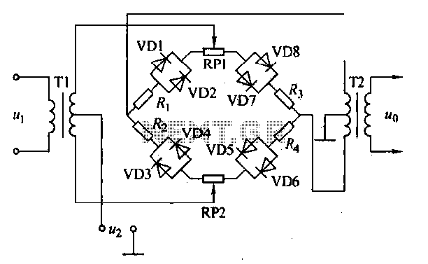
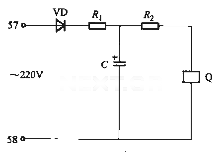
An AM diode ring circuit consists of four diodes arranged in a ring configuration, commonly referred to as a diode ring modulator circuit. This circuit offers significant advantages due to the characteristics of the diodes and the use of...