
Water level indicator circuit using CMOS ICs

The water level indicator circuit operates on a straightforward principle utilizing the conductive properties of water. The circuit is primarily composed of the CMOS IC CD4066, which serves as a quad bilateral switch, facilitating the control of LED indicators based on water levels. The circuit includes a series of resistors, specifically the 180 kΩ resistor, which plays a crucial role in ensuring that the switch remains open when the water level is low, thus keeping the LEDs off.
As water fills the tank, it completes the circuit between the sensing wire and the switch (S1), allowing current to flow and subsequently turning on LED1. The sequential illumination of additional LEDs (LED2, LED3, and LED4) is achieved through a cascading arrangement that detects incremental water levels. Each LED corresponds to a specific range of water levels, providing visual feedback regarding the tank's status.
When the water reaches its maximum level, it triggers the transistor BC148. The base of the transistor receives a high signal, causing it to enter saturation and activate the buzzer, which serves as an audible alarm to notify users that the tank is full. The inclusion of an SPST switch allows for manual control to deactivate the buzzer when necessary.
This design is particularly beneficial for applications in residential and agricultural settings where monitoring water levels is essential for efficient resource management. The simplicity of the circuit makes it easy to assemble and implement, while the use of common electronic components ensures low production costs. Overall, this water level indicator circuit is an effective solution for continuous monitoring and alerting for overhead water tanks.A very simple low cost water level indicator circuit can be designed using this schematic circuit. This water level indicator is based on a simple CMOS IC CD4066 and indicates the amount of water present in the overhead tank and also gives an alarm when the tank is full. When the water is empty the wires in the tank are open circuited and the 180 K resistors pulls the switch low hence opening the switch and LEDs are OFF. As the water starts filling up, first the wire in the tank connected to S1 and the + supply are shorted by water. This closes the switch S1 and turns the LED1 ON. As the water continues to fill the tank, the LEDs2, 3 and 4 light up gradually. When the water is full, the base of the transistor BC148 is pulled high by the water and this saturates the transistor, turning the buzzer ON.
The SPST switch has to be opened to turn the buzzer OFF. 🔗 External reference
Related Circuits

An RF power amplifier is an electronic amplifier used to convert a low-power radio-frequency signal into a larger signal of significant power, typically for driving the antenna of a transmitter. It is optimized for high efficiency, high output power...
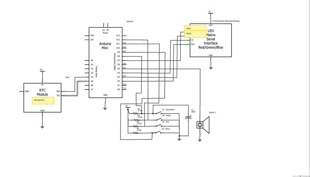
The device is designed to promote respectful time management during meetings, particularly useful in ship-room or SCRUM meetings. The following is a list of components required, including links for purchasing specific parts. It is advisable to check eBay or...
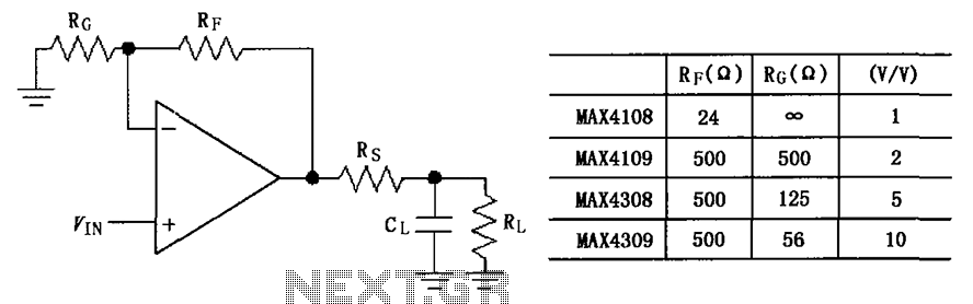
The circuit depicted in the figure employs the MAX4108/4109/4308/4309 operational amplifiers with a capacitive load driving circuit isolation resistor (Rs). While the MAX4108/4109/4308/4309 exhibits excellent AC characteristics, it is not optimized for driving high-load electrical resistances. A significant reactive...
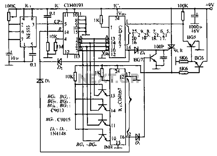
The circuit consists of an oscillator, a counter, and an Iseki circuit divided into three parts. The oscillator is based on the NE555 timer and several external RC components, generating a pulse signal for the counter. The instantaneous power...

PARTS LIST C1 0.22 µF (224) C2 22nF (223) C3 10nF (103) C4 27pF C5 22pF C6 3.3nF (332) C7 180pF (181) C8 330pF (331) C9 3.3nF (332) C10 150pF (151) C11 82pF C12 68pF C13 220pF (221) C14...
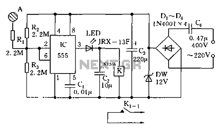
The touch sensor switch circuit diagram features a step-down rectifier circuit, a 555 timer, and flip-flops. When a hand touches the metal sheet A, the sensor signal activates the internal comparator of the 555 timer, setting the output to...