
Analog circuit enforces slow servo response

The described circuit is a sophisticated analog control system designed to manage the throttle of miniature turbojet engines, ensuring gradual adjustments to avoid abrupt changes that could lead to engine failure. The integration of a 555 timer IC with an LTC2054 op-amp allows for precise control of the pulse width modulation (PWM) signal that drives the throttle. The system operates by receiving a pulse-width modulated signal from a radio control, which is converted into a corresponding analog voltage via the integrator. The adjustable parameters, including response rate and servo direction, allow for fine-tuning based on specific application requirements.
The use of a low-dropout regulator ensures stable operation even under variable battery conditions, making the circuit robust for use in dynamic environments. The precision rectification and gain control provided by the amplifiers enhance the circuit's ability to respond accurately to input variations. The inclusion of temperature compensation ensures that the circuit maintains performance across a range of operating conditions, thus preserving the reliability of the throttle control function.
This circuit is particularly advantageous in applications where precision and safety are paramount, such as in remote-controlled aircraft, where rapid throttle adjustments can lead to dangerous situations. By providing a smooth and adjustable servo response, this circuit enhances the overall control and stability of the miniature turbojet engine, significantly reducing the risk of flameouts and mechanical failures during flight.The all-analog circuit presented controls the rateat which a miniature turbojet engine can be throttled. Increasing or decreasing the throttle too quickly on a miniature turbojet engine, or any jet engine, can lead to quick failure in flight, causing expensive repairs and potential safety problems due to flameouts.
This circuit can be used as an analog backup circuit in a microcomputer-based throttle controller, or as the primary throttle-rate controller. The response rate, servo direction, clockwise (CW) and counterclockwise (CCW) gain (end points) and servo-centering parameters are adjustable.
This circuit, Figure 1, takes a received radio-control, incoming positive-going pulse which varies from 1 to 2 ms (the standard for most aircraft radio-control systems), at a fixed frame rate of 20 ms, integrates it over time. It uses the output of the integrator to control the output pulse width of a 555 IC monostable multivibrator.
The rate of pulse-width change is determined by the effective integrator time constant, R24 and VR1 in series, C1, and the duty cycle of the incoming pulse stream. Q1 is switched on for the duration of the positive-going pulse, applying +5 V to the integrator-input resistor, R24 and VR1 in series.
The circuit is designed such that a point will be reached where the effective charge rate-based on the input pulse width-and the reset/discharge rate of integration capacitor C1 by R1, balances for each positive-pulse duration, causing the output of integrator U3 to stabilize at a DC value as a function of the received-pulse width. An LTC2054 zero-drift op amp is used for the integrator. This op amp has an ultralow input bias current, ±1 pA (typical) and ±150 pA (maximum), offset voltage of 3 V and a drift spec of 30 nV/ °C (maximum>.
The open-loop gain of 140 dB (typical), power supply rejection ration (PSRR) and common-mode rejection ratio (CMRR) of 130 dB (typical), and a low noise spec of 1. 6 VP-P (typical) combine to characterize an op amp which is very well suited for the integration function.
The LT1120A low-voltage regulator includes a reset output used to hold off any output from U5, until the integrator output has had time to reach an output after one full time constant. The low dropout (LDO) regulator delivers a well-regulated 4 V from a 4. 8 V NiCd battery, even when the battery voltage is pulled down to 4. 2 V under heavy loads, such as using high-current digital servos. Amplifier U4: A provides gain and the ability to independently adjust the CW and CCW endpoint travel.
Diodes D1 and D2 effectively split the feedback path when the input signal is above or below the 2. 35 V reference level on pin 5. This circuit is a basic precision rectifier used as a gain splitter. Amplifier U4: B buffers and sums the CW and CCW signals. Amplifier U4: C, a ±1 gain amplifier, adds the servo-reverse function and provides a servo center-position adjustment. Amplifier U4: D and resistors R11 and R12 generate the 2. 35 V pseudo-ground reference for the single-supply op amps. The 2. 35 V value is chosen to be centered within the op amp`s input common-mode range to give symmetrical output swing.
The centering adjustment VR4 sets the input control voltage of the 555 timer IC to its midpoint. An LM334 constant-current source set to 16 A charges timing capacitor C11 with a constant current to achieve linear response to the input pulse. D3 and R14 are used to negate the 10 mV/ °C temperature coefficient of U6 the LM334. Two LMOS TC7S14F Schmitt inverters, used for signal buffering, complete the circuit. This circuit provides a very smooth, adjustable servo response wi 🔗 External reference
Related Circuits
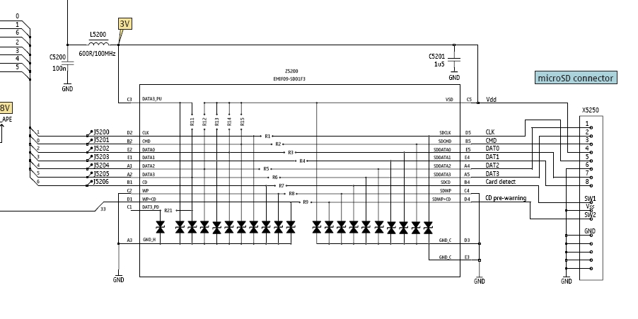
In this tutorial, the functioning of the memory card circuit in mobile phones will be explored. The previous post discussed the pin-outs and types of memory cards utilized in cellular devices. The accompanying block diagram illustrates how the removable...
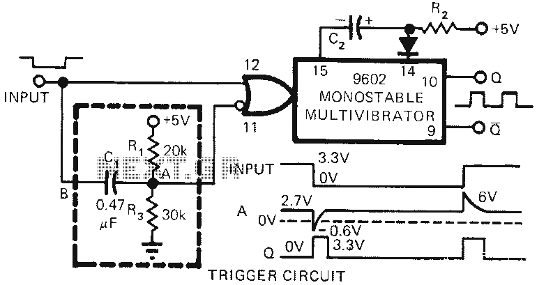
The 9602 multivibrator circuit can trigger either the rising edge or the falling edge of a square wave, but not both simultaneously. To enable double-edge triggering, two additional resistors and a capacitor can be employed. When the input signal...
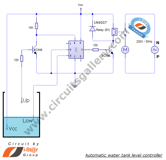
The automatic water level controller circuit is a straightforward engineering project that can automatically switch a domestic water pump on and off based on the water level in a tank. This motor driver circuit can be implemented at home...
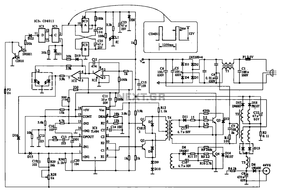
The TN-1 Intelligent Negative Pulse Charging Circuit is a sophisticated device designed for efficient battery charging. It operates as a half-bridge charger, which is a common configuration in such circuits. The negative pulse charging mechanism is facilitated by a...
This temperature-controlled relay circuit is a simple yet highly accurate thermal control circuit that can be used in applications requiring automatic temperature regulation. The temperature-controlled relay circuit operates by monitoring the ambient temperature and activating or deactivating a connected load...

A Countdown Timer Circuit is a project submitted by a group of students for their ECE 130 - Computer Application class on August 31, 2006, at the University of St. La Salle, Philippines. The seven-segment decoder is utilized in...