
Reversing the operation of the two reverse brake circuit

The C650-2 lathe brake control circuit is designed to manage the braking mechanism of a lathe machine effectively. This circuit incorporates a speed control relay that plays a crucial role in modulating the braking response based on the operational speed of the lathe.
The primary components of this circuit include the speed control relay, which is responsible for detecting the rotational speed of the lathe spindle. When the spindle speed reaches a predetermined threshold, the relay activates, allowing for the application of the brake. This ensures that the braking force is applied smoothly and efficiently, preventing abrupt stops that could damage the workpiece or the machine itself.
In addition to the speed control relay, the circuit may also include safety features such as limit switches that ensure the brake is only engaged when the lathe is in a safe operational state. The control logic can be implemented using a combination of mechanical relays or a programmable logic controller (PLC), depending on the complexity required for the application.
Wiring for the circuit should be laid out to minimize interference and ensure reliable operation. Proper grounding and the use of appropriate gauge wires are essential to handle the current loads associated with the brake system. Additionally, protective components such as fuses or circuit breakers should be integrated to safeguard against overcurrent situations.
Overall, the C650-2 lathe brake control circuit exemplifies a well-designed system that integrates speed monitoring and braking control, enhancing both the safety and efficiency of lathe operations. Circuit shown in Figure 3-129. The circuit is C650-2 lathe brake control circuit. Kv using speed control relay.
Related Circuits
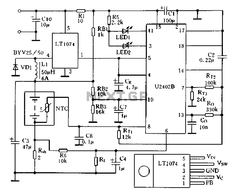
Charging circuit from the DC power supply switching power supply control The charging circuit described is designed to operate with a DC power supply, utilizing a switching power supply control mechanism. This type of circuit is commonly employed in applications...
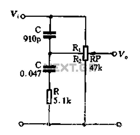
Figure 1-89 illustrates a loudness control circuit. A potentiometer is connected to ground, with 30% of the total resistance at the tap. When the slider arm is adjusted to the tap position, a midrange attenuation of 30 dB is...
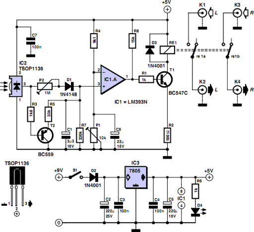
Many households still have tube-type television sets. Connecting one of these large televisions to a stereo system to enhance sound quality is generally straightforward, as numerous SCART to Cinch adapters are available in accessory stores. However, some television sets...
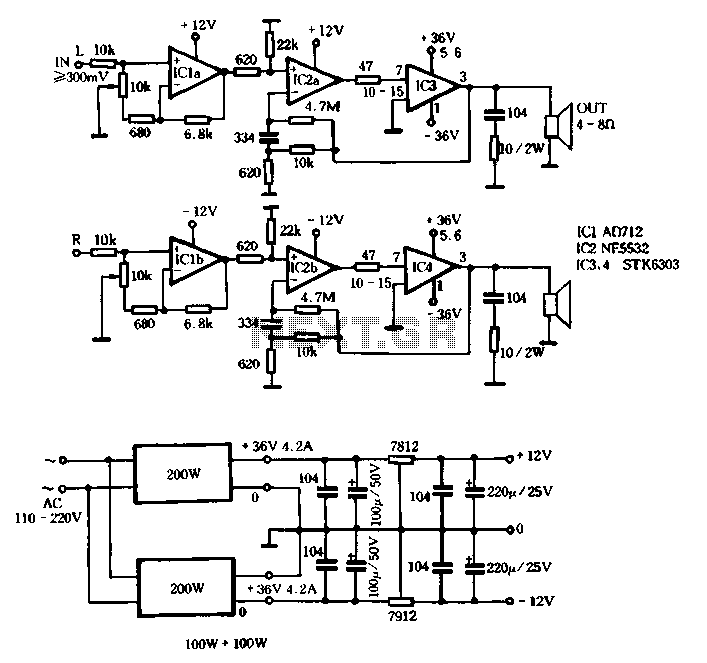
The T amplifier circuit schematic section is illustrated in Figure 3-51. It utilizes the Japan Sanyo STK6303 Pina, which is a high-power thick film integrated circuit. The maximum power supply voltage is 36V, and the output current can reach...
LEDs lining the headliner will fade in when the door is opened and fade out when the door is closed. The necessary components include a circuit to utilize 12V power from the vehicle to illuminate 15 LEDs and control...
Figure 4-13 illustrates a modified version of a standard attenuated tone control from the pitch selector. It features two amplification stages of amplifiers 10 and Icl utilized as line amplifiers. Capacitor C2 is employed to compensate for tone attenuation...