
ramped magnetic field circuit for a miniature mass spectrometer

The R-2R ladder DAC is a widely used circuit for converting digital signals into analog voltages. This circuit employs a network of resistors arranged in a specific manner to achieve the desired output. The R-2R ladder consists of two resistor values: R and 2R. Each bit of the digital input corresponds to a switch that connects either to a reference voltage (V_ref) or ground (0V).
In the context of an 8-bit DAC, there are 8 digital inputs, each controlling a switch. When a switch is connected to V_ref, it contributes to the output voltage, while connecting to ground eliminates its contribution. The output voltage is calculated based on the binary representation of the inputs, where each bit represents a different weight in the overall voltage calculation. The most significant bit (MSB) has the highest weight, while the least significant bit (LSB) has the lowest.
For the timing aspect, with a specified ramp time of 50 seconds, the circuit must increment the output voltage level every (50/256) seconds, allowing for a smooth transition across all 256 levels. This timing can be managed using a microcontroller, such as an Arduino, which generates the necessary control signals to toggle the switches in the R-2R ladder.
The precision of this DAC largely depends on the tolerance of the resistors used. It is essential to use high-precision resistors to ensure that the output voltage levels are accurate and consistent. Furthermore, the circuit can be enhanced by adding a low-pass filter at the output to smooth out any rapid fluctuations in voltage, resulting from the switching of the digital inputs.
In summary, the R-2R ladder DAC provides an efficient means of converting digital signals to analog voltages, with the Arduino controlling the timing and sequence of the output levels to create a smooth ramp waveform. The schematic representation created using Fritzing visually illustrates the arrangement of the resistors and the connections to the Arduino, facilitating a clear understanding of the circuit's operation.The general idea is to space the time internals to increment the DAC output values. There would be 256 levels since there are 8 digital outputs from the Arduino board. Therefore, for an 8-bit, 50s ramp time for example, the way to generate a digital ramp waveform is to increment every level per (50/256)s. No matter what the code will be, a DAC is required to convert digital signal to analog signal. An R-2R Ladder is a simple and inexpensive way to perform digital-to-analog conversion, using repetitive arrangements of precision resistor networks in a ladder-like configuration. Now I use fritzing to draw the schematic of R-2R ladder DAC circuit. 🔗 External reference
Related Circuits
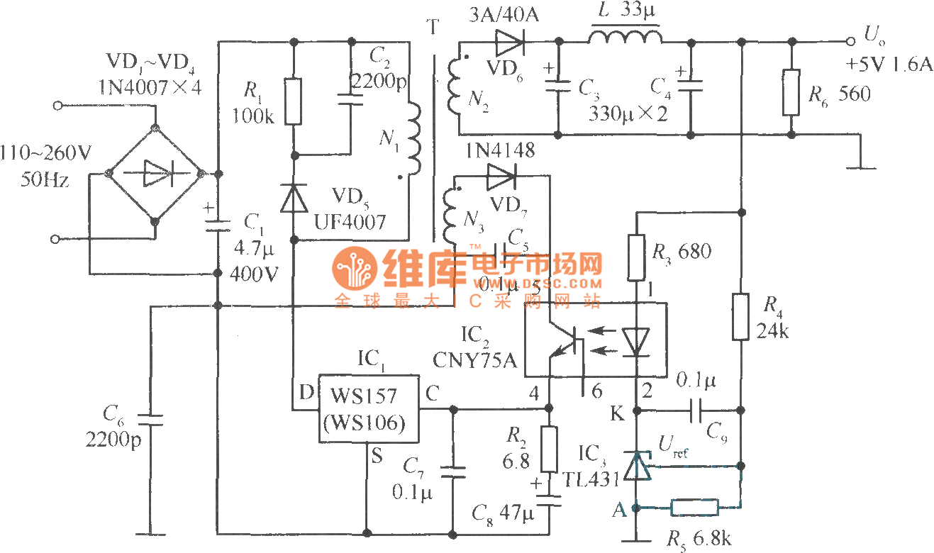
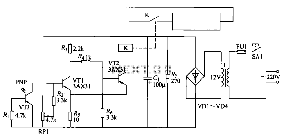
The +5V, 1.6A precision switching power supply circuit is depicted in the figure. This circuit utilizes a photoelectric coupler (CNY75A) and an adjustable precision parallel regulator (TIA31). R3 serves as the current limiting resistor, while R4 and R5 function...
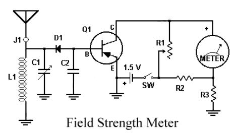
This circuit utilizes a single 1.5V battery. The capacitor C1 must be adjusted for optimal peak reading. To operate the circuit, the transmitter and meter should be turned on. The circuit is designed to operate efficiently with a single 1.5V...
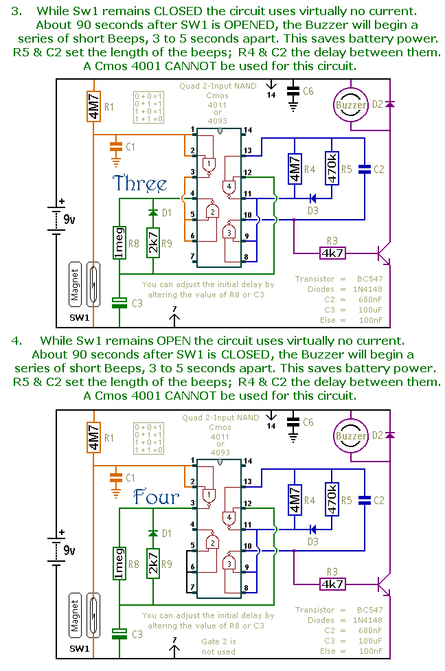
This is a collection of compact, self-sufficient alarm circuits designed for low standby current, making them ideal for battery operation. Some circuits are activated by normally-open and normally-closed switches, while others respond to variations in light or temperature. This...
Typical segment display LEDs consume around 25 mA for each segment and should be limited to this current with resistors. For a six-digit display to be current limited, at least 42 series resistors are needed. The brightness of the...
With the advent of modern integrated circuits (ICs), sophisticated circuits today are no longer required to be complex and lengthy. The chips themselves contain most of the intricate circuitry built-in and can independently perform the desired functions. For instance,...
The cutter is safeguarded by a printed circuit phototransistor designed to prevent accidental activation of the cutter switch during manual feeding. In the event of manual feeding, the automatic paper cutter can be controlled to shut down. A relay...