
random generator

The generator circuit leverages the inherent unpredictability of avalanche noise, which is generated in a reverse-biased PN junction, to produce true random numbers suitable for applications requiring high levels of security, such as encryption. The circuit's architecture begins with a transistor that captures the avalanche noise, which is then amplified by a second transistor. Following this, two ALS04 inverters are employed in a biased linear configuration, functioning as operational amplifiers to further enhance the signal strength before passing it to a third inverter for additional amplification.
The PIC 16F648A microcontroller plays a crucial role in this setup. It is equipped with a comparator that effectively filters the noise signal, allowing the microcontroller to detect significant voltage spikes indicative of random noise events. The comparator's rapid response time is critical in ensuring that no spikes are missed, which is essential for generating a reliable stream of random numbers. The software running on the PIC is designed to count the number of detected spikes in a specified time interval, translating this count into binary output based on parity—outputting a '1' for even counts and a '0' for odd counts.
The inclusion of switches for output mode selection and an XOR mask enhances the versatility of the generator. The output mode switch allows users to choose between different formats of random data, while the XOR mask serves to mitigate any inherent bias in the output, ensuring a more uniform distribution of bits. This capability is particularly important in cryptographic applications where predictability can lead to vulnerabilities.
The fabrication process of the circuit board involves careful attention to detail, especially in the toner transfer method, which is sensitive to the ironing technique used. The recommendation to fill open areas with shapes is a practical approach to reduce the amount of exposed copper during etching, thereby optimizing the etching process. The final assembly of the components is straightforward, with clear guidelines for soldering and power connections, ensuring that the circuit operates reliably with the specified power sources.
The initial testing results indicate the generator's efficacy, with a good distribution of random bytes and a favorable pass rate in the NIST test suite. Further testing with the XOR mask is anticipated to enhance the performance of the generator, providing a robust solution for applications requiring true random number generation.This generator uses avalanche noise, and is based on a design by Will Ware. Herein are instructions as to how you can use a pic chip to analyze a noise source and output random data serially. I`ve included circuit diagrams as well as links to instructions for fabricating your own board. There are two types of random numbers: true and pseudo. Pseu do random numbers are created by an algorithm. The problem with this is that if someone knows what algorithm you use, it is theoretically possible predict what numbers you will create. True random number generators create sequences that are impossible to predict. They use random physical phenomenon as their source or randomness. They are used for encryption and micro psychokinesis research. "This circuit uses avalanche noise in a reverse-biased PN junction, the emitter-base junction of the first transistor.
The second transistor amplifies it. The first two ALS04 inverters are biased into a linear region where they act like op amps, and they amplify it further. The third inverter amplifies it some more. " The Pic chip is for analyzing the noise and sending out random bits. I used a 16F648A because it has a comparator. The signal going into the pic has fuzz between 1 and 2 volts and spikes that go up to 3 volts. It`s these spikes we want to measure. The comparator will cut out the fuzz and interrupt the pic whenever there is a spike. (I tried the pic`s ADC but the comparator seemed more responsive). The pic code works like this: the pic records the number of spikes it detects in a short time interval.
If there are an even number of spikes it outputs a 1, an odd number a zero. Also, the board has input for two switches. These control the output mode and the XOR mask. The mode switch sets the generator to output either random bytes or ascii 1`s and 0`s. The XOR mask XOR`s the output of the generator with a string of alternating 0`s and 1`s. This reduces bias. The switch turns the mask on or off. To create the board I used a laser-printer transfer technique. I intend to write my own instructions, but until then I refer you to these already existing guides: Concise, Verbose, and Mine. Read Concise first to get an overview of the process. If you are going to make your own board, read Verbose in detail, especially the ironing section. Surprisingly, ironing is the trickyest part. If it is not done correctly the toner will not transfer completely to the copper. Also, what is not mentioned in these guides is that when creating a board, you should fill in open areas with shapes.
As you can see in my board, I have filled in most of the open space including the area around the circuit. The benifit of this is that less copper is exposed during etching, and therefore less etchant and *a lot* less time is needed to etch the board.
Here is the components diagram. Put the components through the holes on the side of the board without the copper. Solder them. My board requires a 12V power supply, and I wire it to +12V and GND holes. It should also work with a 9V battery. As of 12/14/05 I haven`t had the chance to extensively analyze the output. I have produced a historgram of the random bytes and it looks good. The ratio of zero`s to one`s also seems in check. I ran about a million bits without the XOR mask through the NIST test suite, and it appeared to pass about 75% of the tests. I`m going to try again with the XOR mask and see if it makes an improvement. 🔗 External reference
Related Circuits
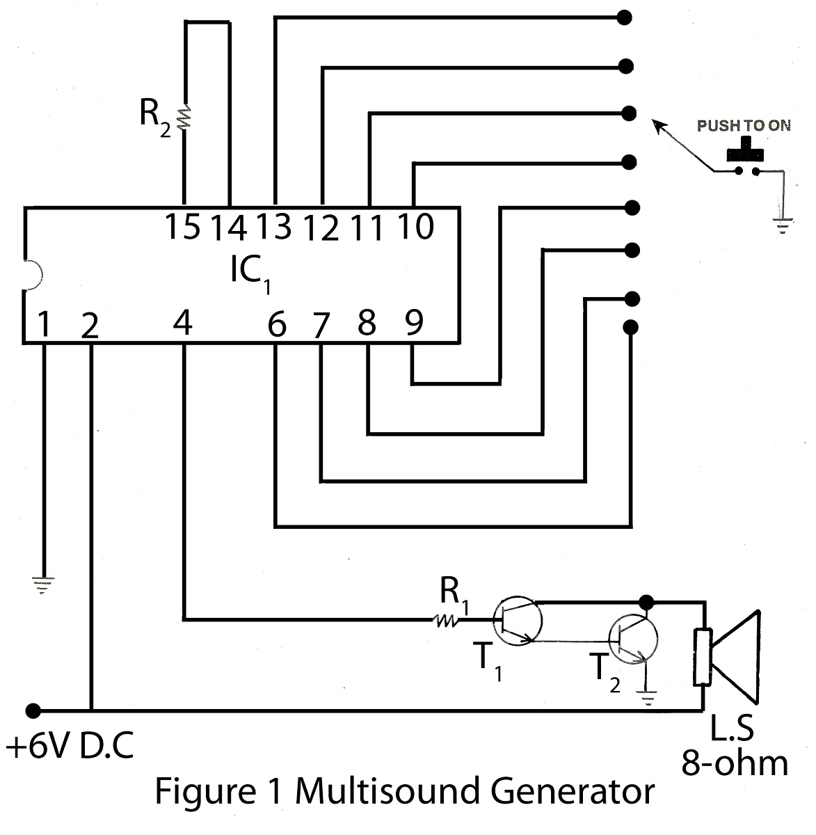
The multisound generator is an intriguing project within the alarm system series. This generator produces eight different types of sounds, and it includes a circuit diagram for various electronic projects. The multisound generator circuit is designed to create a variety...

This circuit generates a linear sawtooth waveform with a frequency range from 30 Hz to 3,000 Hz. Q1 acts as a constant-current source that charges capacitor C1 until the output level at the emitter of Q3 triggers operational amplifiers...
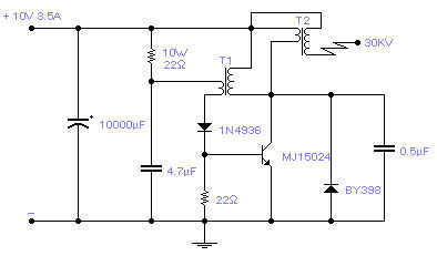
Easy to build, this high voltage generator is capable of generating up to 50KV but the breakdown voltage of the coil limits the voltage to a value somewhat lower. T2 is the ignition coil of a car and also...

The voltage Vc1 increases linearly when the pull-up resistor RA in the monostable circuit is replaced with a constant current source, resulting in a linear ramp. The circuit for generating the linear ramp and the corresponding waveforms are illustrated...

The schematic diagram below illustrates a high voltage generator circuit. This circuit employs a 4049 hex inverter configured as an oscillator, and it can utilize an ignition transformer from an automotive engine. A fly-back transformer may also be suitable....
The following design is capable of overlaying the time and date onto any existing PAL (or optionally NTSC) composite video signal. It is housed in a very neat and compact standard moulded casing and has standard 75ohm RCA video...