
555 IC Linear Ramp (Sawtooth) Generator/Oscillator
 Generator/Oscillator")
The described circuit utilizes a monostable configuration where the replacement of the pull-up resistor RA with a constant current source allows for the generation of a linear voltage ramp across the capacitor C1. This configuration is particularly useful in applications requiring precise timing and linear voltage changes. The PNP transistor serves as the active element that regulates the current flowing through the capacitor, ensuring that it remains constant.
When the timer is triggered, the PNP transistor is activated, allowing a steady current to flow through the capacitor. The relationship between the current, capacitance, and the resulting voltage across the capacitor is described by the formula V = I * t / C, where I is the constant current, t is the time duration, and C is the capacitance.
In this case, the specified parameters yield a ramp rate of 9.77V/ms, indicating that the voltage across the capacitor increases at this rate as long as the current remains constant. This behavior is critical in timing circuits, pulse generation, and signal conditioning applications where a predictable voltage change is required.
The schematic diagram referenced from Philips Semiconductors Application Notes provides a visual representation of the circuit, illustrating how the components interact to produce the desired linear ramp output. This design can be adapted for various electronic applications, including waveform generation, analog signal processing, and timing control systems, making it a versatile solution in electronic engineering.The Vc1 increases linearly when the pull-up resistor RA in the monostable circuit is replaced with constant current source, generating a linear ramp. The linear ramp generating circuit and the generated linear ramp waveforms illustration is shown in figures below.
The current flowing through capacitor C1 becomes a constant current generated by PNP transistor and resistor when the trigger starts in a timer configured as shown in figure below. In other words, we can obtained the gradient of the linear ramp function appearing across the capacitor by using the constant current flowing through the capacitor. The gradient of the ramp function at both ends of the capacitor is S = 0. 215m/0. 022 = 9. 77V/ms if the constant current flow through the capacitor is 0. 215mA and the capacitance is 0. 02uF. [Circuit`s schematic diagram source: Philips Semiconductors Application Notes] We aim to transmit more information by carrying articles.
Please send us an E-mail to wanghuali@hqew. net within 15 days if we are involved in the problems of article content, copyright or other problems. We will delete it soon. 🔗 External reference
Related Circuits
A 1 Hz pulse frequency generator utilizes the widely used timer IC 555 configured as an Astable Multivibrator. The output pulses can be visually indicated by an LED. An Astable Multivibrator, often referred to as a free-running Multivibrator, is...
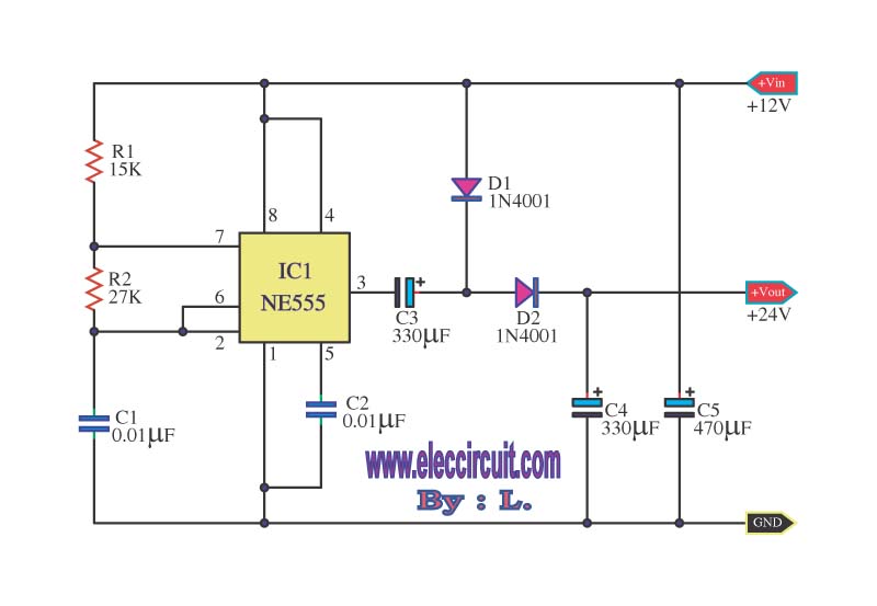
This is a simple voltage doubler circuit that converts 12V DC into 24V DC. It utilizes the popular NE555 timer IC along with a few additional components. The circuit can provide approximately 50mA of current, making it suitable for...
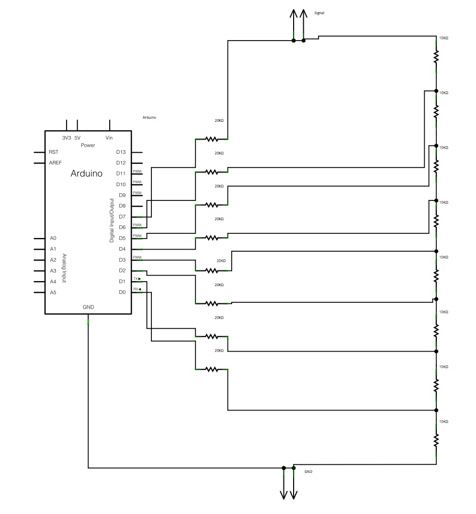
The main concept is to space the time intervals to increment the DAC output values. There are 256 levels since there are 8 digital outputs from the Arduino board. Therefore, for an 8-bit resolution and a 50-second ramp time,...
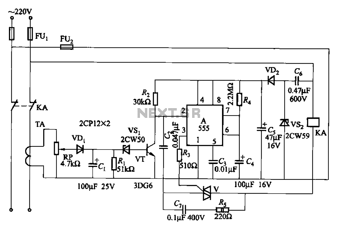
The 555 limit circuit, which is an integrated electrical circuit, is designed to manage large electrical loads. It automatically disconnects power when the load exceeds a predetermined threshold. Once the load is reduced below this threshold, power is restored...
How to create a hydrogen generator using a 555 timer circuit with Pulse Width Modulation (PWM). This PWM circuit can generate hydrogen on demand. The hydrogen generator circuit utilizing a 555 timer operates by controlling the duty cycle of the...
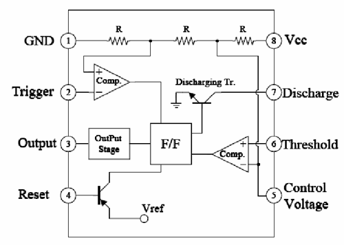
Most circuits operate based on a flip-flop principle. Instead of using a dedicated flip-flop chip, a 555 timer chip can be utilized, as it contains a single flip-flop and several comparators. After researching various resources, including Forrest Mims' electronics...