
Ratio Detector for FM Demodulation

FM detectors are critical components in communication systems, particularly in frequency modulation (FM) applications. The operation of these detectors, while sometimes perceived as complex, can be understood through the examination of their underlying principles and components.
A ratio detector is a specific type of FM detector that converts frequency variations in an incoming signal into amplitude variations. This process typically involves several key elements: a diode, a low-pass filter, and a phase-locked loop (PLL). The incoming FM signal is first fed into the diode, which rectifies the signal and allows for the extraction of the envelope. This envelope reflects the instantaneous frequency changes of the FM signal.
After rectification, the low-pass filter smooths the rectified signal, effectively removing high-frequency components that are not relevant to the desired output. The output from the low-pass filter is then analyzed to determine the amplitude variations that correspond to the original frequency modulated signal.
The ratio detector is particularly valued for its ability to provide a stable output even in the presence of noise, making it suitable for various applications, including radio receivers and audio broadcasting systems. Understanding the operation of these detectors is crucial for engineers designing communication systems, as it allows for the optimization of signal processing and reception quality.
In summary, the ratio detector serves as an essential tool in demodulating FM signals, translating frequency changes into usable amplitude variations, while maintaining robustness against noise interference. This functionality is foundational in many modern communication technologies.This view is not far from wrong because the operation of FM detectors is widely regarded as mysterious. The ratio detector to find out how it works, without.. 🔗 External reference
Related Circuits
The GLMDPCB motion detector board is a double-sided etched, screened, and drilled printed circuit board designed for the GLMDA motion detector circuit illustrated in the schematic below. The circuit can be constructed in its entirety or in part. For...
This homemade metal detector circuit will assist in locating objects made of materials with relatively high magnetic permeability. It is not suitable for detecting certain metals. This metal detector circuit operates on the principle of electromagnetic induction, utilizing a coil...
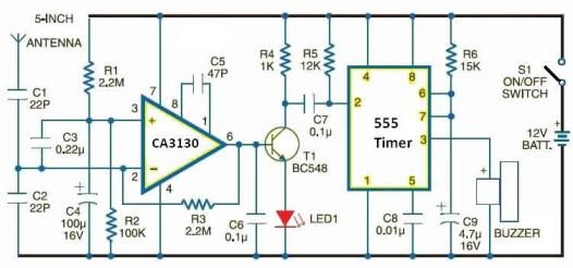
This electronic schematic allows for the design of a simple cellular phone detector circuit capable of sensing the presence of an activated mobile phone from a distance of 1.5 meters. The capacitor C3 should have lead lengths of 18...
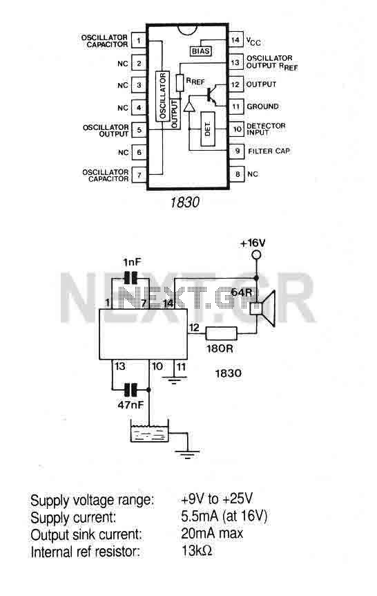
The IC is ideal for detecting the presence, absence or level of water or other conducting liquids. A detector determines the presence or absence of fluid by comparing the resistance of the fluid with the IC's internal reference resistance....

When the receiver is tuned to a medium wave radio station, feedback howl caused by the transmitter may occur when the coil and radio are positioned above or near a metal object. The search head is constructed from a...
This circuit can be constructed using easily accessible, low-cost components, some of which might even be found in a collection of spare parts. The circuit in question is designed to utilize common electronic components, making it an ideal project for...