
RC 4-Channel FM receiver

The described receiver is designed for applications requiring lightweight and compact components, making it ideal for slow-flying aircraft and small boats. The specifications indicate a weight of 9 grams, which is critical for maintaining the overall weight of the model while ensuring sufficient performance. The dimensions of 32 x 25 mm highlight its compactness, allowing for easy integration into various designs without significantly altering the structure or aerodynamics of the vehicle.
In terms of functionality, the receiver is likely to operate within a limited frequency range, which is suitable for low-speed applications. This reduced range can minimize interference and enhance the reliability of signal transmission in environments where high-frequency signals may be disrupted. The receiver may utilize a simple antenna design to optimize its performance, ensuring a stable connection with the transmitter.
The application in slow-flyers suggests that the receiver is capable of handling lower speeds and may be optimized for long-range control at these speeds, providing a balance between range and control precision. In small boats, the receiver's lightweight design ensures that it does not adversely affect the vessel's buoyancy or maneuverability.
Overall, this receiver represents a practical solution for hobbyists and professionals seeking reliable communication in lightweight models, emphasizing the importance of size and weight in the design of remote-controlled devices.This small receiver with reduced range (weight 9g, dimensions 32 x 25 mm) is suitable for slow-flyer, little boats, etc. 🔗 External reference
Related Circuits
Here is a Tesla coil secondary design: Wind 750 turns of 24-gauge enameled magnet wire onto an 18-inch long piece of 1.9-inch outer-diameter PVC pipe. The large coil has an inductance of approximately 2800 mH and a self-capacitance of...
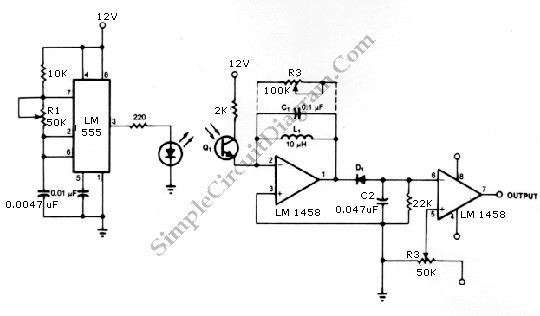
The infrared transmitter and receiver circuit depicted in the schematic diagram can function as a remote control. The transmitter operates as an oscillator circuit, with the frequency adjustable via the R1 potentiometer (or trimmer pot). This oscillation ensures that...
The Demodulating Receiver (A3017) features a 902 to 930 MHz 30-dB amplifier, a downshifter, a 60-dB 50-MHz limiting IF amplifier, a frequency discriminator, and an amplitude demodulator. The A301701A circuit board also includes additional copies of the A3016SO SAW...
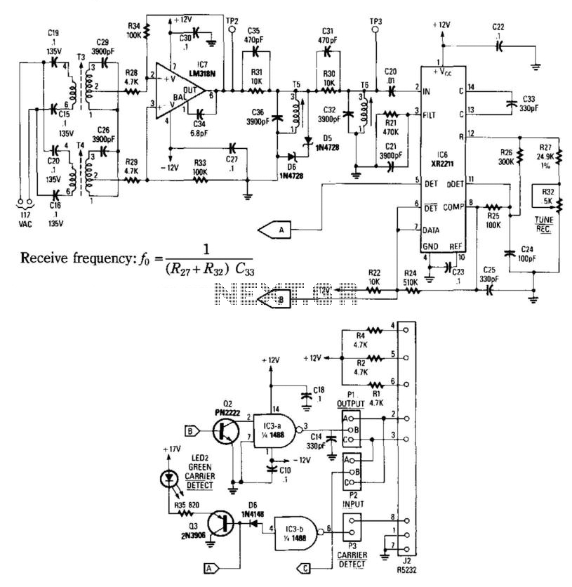
This receiver consists of an input network, amplifier IC7, FSK PLL detector IC8, and output amplifier/interface circuits Q2, Q3, IC3A, and IC3B, which include a 1488 Quad RS232 line driver for the carrier-current signal. The tuned amplifier IC7 amplifies...
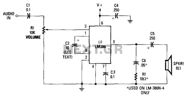
This simple receiver AF amplifier can supply several hundred milliwatts to an 8-ohm speaker. The gain is approximately 200X. If high gain is not required, C2 can be removed, resulting in a gain of 20. R1 and C6 are...
The TDA7088T can be used in mono portable and pocket radios. This is a bipolar integrated circuit. Here is one of the application circuit diagrams. The TDA7088T is a versatile bipolar integrated circuit designed specifically for mono FM radio applications,...