
TESLA COIL SECONDARY RECEIVER

The described Tesla coil secondary consists of a winding of 750 turns of 24-gauge enameled magnet wire, which is crucial for achieving the desired inductance and resonant frequency. The choice of 24-gauge wire is appropriate as it balances resistance and current-carrying capacity, ensuring efficient performance in high-voltage applications. The PVC pipe serves as a lightweight and non-conductive form around which the wire is wound, with a specified length of 18 inches and an outer diameter of 1.9 inches, providing a suitable structure for the coil.
The inductance value of approximately 2800 mH indicates that the coil is designed to operate effectively in the Tesla coil circuit, allowing for the generation of high-voltage electrical discharges. The self-capacitance of about 20 pF suggests that the coil will have a resonant frequency that can be tuned for optimal performance. Grounding one end of the coil is essential for safety and functionality, as it provides a reference point for the electrical potential and helps to dissipate any unwanted energy.
The placement of a metal ball at the opposite end of the coil serves as a terminal for the high-voltage output, where the electric field can build up and create impressive discharges. The selection of a drawer pull knob or doorknob as the terminal is practical, as these items are readily available and can effectively serve the purpose of enhancing the electric field around the coil.
This configuration allows for experimentation with Tesla coil designs, providing insights into the principles of electromagnetic induction, resonance, and high-voltage generation. Proper safety precautions should be observed when working with Tesla coils, as they can produce potentially dangerous voltages and currents.Here`s a Tesla-coil secondary to try: Wind 750 turns of 24-gauge enameled magnet wire onto an 18 long piece of 1.9 outer-diameter PVC pipe. The large coil has an inductance of about 2800 mH, with a self-capacitance of about 20 pF. One end of the coil should be earth grounded. Put a metal ball (a drawer pull knob or doorknob) at the other end. Now attach it.. 🔗 External reference
Related Circuits
An FM regenerative receiver using a single FET and one audio amplifier IC. The described circuit is an FM regenerative receiver, which is designed to demodulate frequency modulated signals. The core component of this receiver is a Field Effect Transistor...
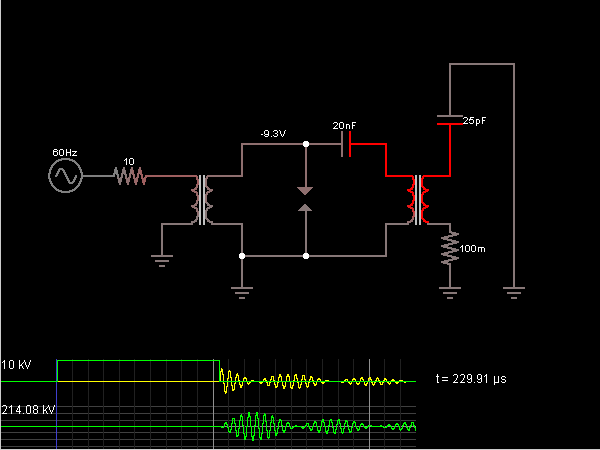
This is the Tesla Coil circuit diagram with a detailed explanation of its working principles. The electronic circuit simulator aids in designing the Tesla Coil circuit and simulating it online for better understanding. The Tesla Coil is a resonant transformer...
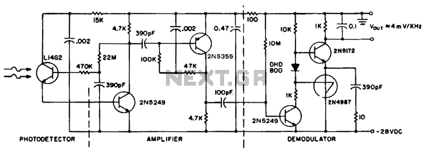
To achieve maximum range, the receiver should be constructed similarly to a radio receiver front end, as the signals received will exhibit comparable frequency components and amplitudes of the photodiode current. The primary limitation on the receiver's performance is...
Nearly all AM radio manufacturers utilized this specific circuit from approximately 1948 to 1963. There is a growing interest in collecting these radios as antiques. Credit for the creator of this figure and caption is sought, but the source...
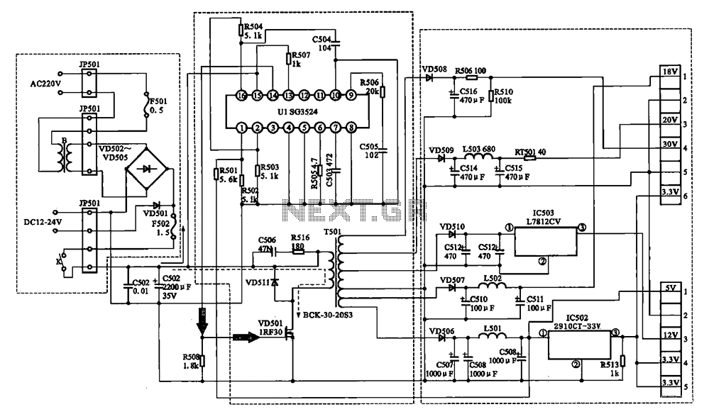
The Changhong DVB-2000 digital satellite receiver features a switching power supply circuit. This circuit primarily comprises a power input section, an oscillation switching circuit, and a DC output section. The power input circuit receives 22V AC from a step-down...
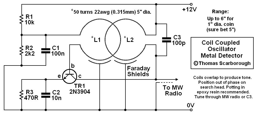
A coil-coupled operation metal detector constructed from commonly available components, utilizing a standard medium receiver as the detection unit. The coil-coupled operation metal detector functions by employing a transmitter coil and a receiver coil that are magnetically coupled. The transmitter...