
Infrared Transmitter-Receiver with 555

The infrared transmitter circuit is designed to emit modulated infrared signals, which can be received by an appropriate infrared receiver. The core of the transmitter is an oscillator that generates a square wave signal. The frequency of this square wave can be fine-tuned using the R1 potentiometer, allowing for optimal signal clarity and ensuring that the transmitted signal can be easily detected by the receiver.
The receiver circuit is structured as a bandpass filter, which is crucial for isolating the desired frequency from ambient noise. The combination of inductor L and capacitor C forms a resonant circuit, which is finely adjusted to match the frequency of the transmitter. This configuration effectively enhances the signal-to-noise ratio, enabling the receiver to accurately interpret the incoming infrared signals.
In the feedback loop of the op-amp, the diode D1 plays a vital role in signal rectification. It allows the circuit to process weak signals that may otherwise be lost due to the inherent noise in the environment. The op-amp's feedback mechanism is designed to adapt to the voltage drop across the diode, thus maintaining signal integrity.
The final stage of the receiver utilizes another op-amp configured as a comparator. This op-amp compares the incoming signal against a predefined threshold, which can be adjusted using the R3 potentiometer. This adjustment capability is essential for accommodating variations in signal strength and ensuring reliable operation under different conditions. The op-amp requires a dual power supply of +12V and -12V, which is standard for many op-amp configurations, providing the necessary headroom for accurate signal processing.
Overall, this infrared transmitter and receiver circuit is a robust solution for remote control applications, leveraging adjustable components to optimize performance and reliability.Infrared transmitter and receiver circuit shown in the schematic diagram below can be used as remote control. The transmitter is basically an oscillator circuit, and the frequency can be adjusted using R1 potentiometer (or trimmer pot).
This oscillation makes sure if the signal can be distinguished from other source by the receiver. The receiver i s actually a bandpass filter which filter out noise signal. The frequency of this filter is determined by L and C in the feedback path (from output to inverting input of the op-amp). D1 is inserted in the feedback path to enable rectifying very small signal, since the op-amp feedback mechanism will compensate the forward drop voltage of the diode.
The last op-amp is employed as a comparator, with the threshold is adjustable via R3 potentiometer. The op-amp should be supplied with + and 12Volt, and the R3 potentiometer should be supplied with -12V. [Circuit`s schematic diagram source: hobbyprojects. com] 🔗 External reference
Related Circuits
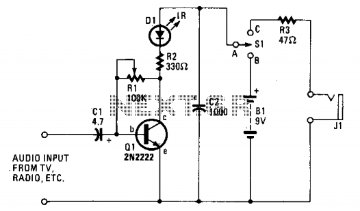
The ultra-simple one-transistor IR transmitter is designed to transmit sound from any 8 or 16-ohm audio source, such as a TV, radio, or tape recorder, using an infrared beam of light. The one-transistor infrared (IR) transmitter circuit operates by modulating...
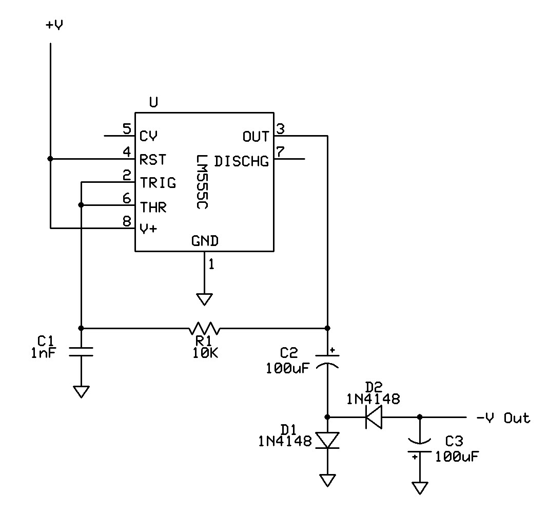
Can a 555 negative supply circuit, like the one below I pulled from another schematic, supply enough negative voltage to an LM324 and an AD736JN? The 555 timer integrated circuit can be configured to generate a negative voltage supply,...
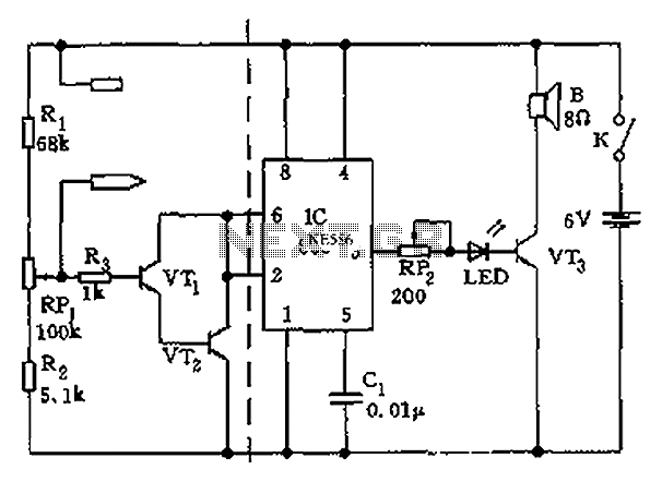
The apparatus consists of a cavers point detection circuit and a triggering display circuit. The cavers instrument functions as a test probe, which, when held in one hand, can detect acupuncture points by touching the skin with another probe....
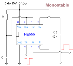
The 555 Timer is an integrated circuit utilized for various functions such as timing, pulse generation, and tone generation, all from a single universal IC. Each pin's function is detailed, and design recommendations are provided as necessary. A Monostable...
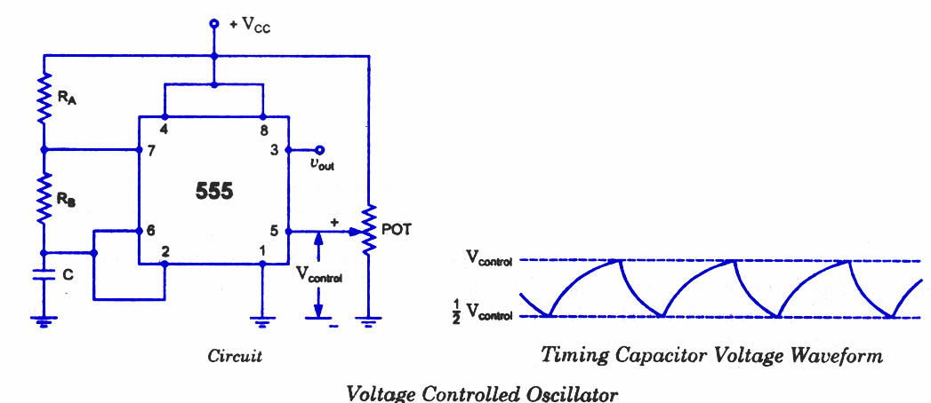
As discussed in previous blog posts, the pin 5 terminal serves as a voltage control terminal, allowing for the adjustment of threshold and trigger levels. Typically, the control voltage is set at +2/3VCC due to the internal voltage divider....
Whenever an easy method is discovered for accomplishing a task, it is essential to document it. Certain projects may require a wireless solution using the Logochip. The following circuit simplifies this process. First, an explanation of the Radioshack 276-640...