
RC oscillator

This function generator circuit is designed to produce a variety of waveforms, including sine, square, and triangle waves, across the specified frequency range of 15 Hz to 30 kHz. The versatility of the circuit allows it to be used in various applications, such as testing audio equipment, simulating signals for control systems, and providing reference signals for other electronic circuits.
The core of the circuit typically utilizes a combination of operational amplifiers (op-amps) and transistors to achieve the desired waveform generation. For the transistor section, the 2N2926 or an equivalent transistor is recommended due to its suitable frequency response and amplification characteristics. The transistor can be configured in various ways, such as in a common-emitter configuration, to amplify the output signal effectively.
To generate different types of waveforms, the circuit may employ a combination of feedback networks and timing components, such as resistors and capacitors, which determine the frequency and shape of the output signal. The frequency of oscillation can be adjusted by changing the values of these passive components. For instance, in a square wave generator configuration, the duty cycle can be controlled by varying the resistor-capacitor (RC) time constants.
In addition to the basic components, the circuit may also include features such as amplitude control, output buffering, and protection diodes to safeguard the transistors from voltage spikes. Proper layout and grounding techniques are essential to minimize noise and ensure stable operation, particularly at higher frequencies.
Overall, this function generator circuit provides a reliable and flexible solution for generating periodic waveforms across a broad frequency range, making it an invaluable tool for electronics testing and experimentation.The circuit covers 15 Hz-30 kHz and is useful as a function generator. The 2N2926 or equivalent transistors can be used.
Related Circuits
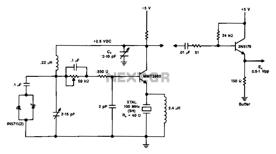
The diagram illustrates a 100 MHz oscillator functioning on the fifth harmonic. To preserve the transistor's gain, it is important to note the increase in the collector's load resistance, Rl, due to the rise in the quartz crystal's internal...
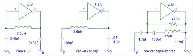
This oscillator does not require biasing components. Only an inductor and various matching or tuning capacitors are needed to set the operating frequency. The active component is the 74HCU04 hex inverter, with only one of the six inverters necessary...
An oscillator circuit is an electronic circuit that produces a periodic signal. The term quadrature refers to a fourth (1/4) phase shift of a full wave cycle (1/4 of... An oscillator circuit is a fundamental component in various electronic systems,...

A simulation of a Colpitts Oscillator circuit using an NPN transistor and other components available in SimElectronics is presented. The feedback ratio is determined by the relative values of the capacitors C1 and C2. The frequency of oscillation is...
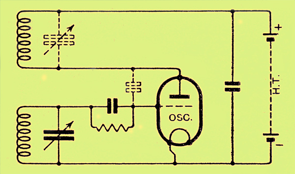
The congestion of the ether is increasing, prompting ongoing efforts to extend communication channels to higher frequencies. Wavelengths as short as 12 meters are now common, but operating below this presents significant challenges. At approximately one meter, the oscillation...
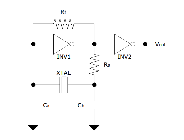
The Pierce oscillator is a simple circuit that, like the ring oscillator, utilizes inverters, though typically only one inverter is required. Its operational principle differs significantly from that of the ring oscillator, as it employs the inverter in its...