
RC Servo Processor

The RC Servo Processor is an integral component for enhancing the functionality of servo-controlled systems in autonomous applications. By allowing for a broader range of motion and speed control, it significantly improves the performance and longevity of servos used in robotic applications. The firmware design, which does not rely on interrupts, ensures that the system remains stable and responsive, making it suitable for real-time applications where precision is critical. The compact PCB design facilitates easy integration into various robotic platforms, ensuring that the processor can be seamlessly incorporated into existing designs without requiring extensive modifications. Additionally, the ability to adjust parameters such as speed limits and sample rates provides flexibility for different applications, allowing for customization based on specific project requirements. This adaptability is essential for engineers and developers seeking to optimize their designs for performance and reliability. The use of common components also aids in reducing costs and simplifying the prototyping process, making the RC Servo Processor a valuable tool in the development of advanced robotic systems.On a continuing mission to build an autonomous sailing robot we needed a way to more rapidly prototype boat designs and wanted to use a standard remote control model control system to save time by using off-the-shelf parts. When controlling servos with microcontroller based electronics you can use the full 180 degrees of rotation; however standard RC
systems typically only support 90 degrees or less. We also needed a way to limit the rotational speed of the servos to prevent wear and damage to parts of the boat. The RC Servo Processor is a simple and small device which sits in between your RC receiver and servo which allows you to control both the rotation range and speed of a servo.
Using only 4 components it is small, light and power efficient. The RC Servo Processor allows you to define the expected range of input from your RC controller and then map that range on to your desired output. This is performed by simply changing some #define statements in the PIC12F source code. The firmware takes care of calculating the required PWM output to the servo by scaling the available input range to the desired output.
Note that the units are in 0. 5uS, so 400uS is 800 (which is why the definitions contain the *2 to make it clearer). Finally there are 2 more supported settings; the rotational speed limit - this can be set to 0 for no limit, or it represents the maximum difference in uS from pulse-to-pulse generated by the RC receiver (so this is typically the maximum change in 1/50th of a second). You can also set up the number of samples which are used to measure the RC controllers output. Since the PIC12F is using the internal oscillator, averaging the readings helps to prevent jitter in the output: // Rotational Speed limitation for output servo // Set to zero for no limit or specify the maximum allowed pulse width variation // per output pulse (in units of 0.
5uS). Note: the actual speed of the output // pulses is dependent on the RC Receiver output, but is typically one pulse per // 20mS (50 pulses per second). #define SERVO_SPEED_LIMIT 0 // Number of samples to average the positive pulse width from (2-5) #define NO_OF_SAMPLES 4 The firmware takes advantage of the fact that RC control systems send a control pulse of around 1-2mS followed by a pause of 20-30mS.
The PIC12F samples the pulse from the RC receiver and then performs all the required calculations for the output pulse during the relatively long gap before sending the pulse to the target. This means that the firmware can be coded without the need for interrupts and helps to keep the timing stable.
The PCB is designed to be as simple and compact as possible. By placing the 5V Regulator and PIC close together the design requires only 2 100nF capacitors to stabilise the power on either side of the regulator. The board draws its power from the servo power feed, however due to the on-board regulator it can operate with battery packs greater than 5Vs without issue: If you like this site and want to help support future projects, or you just want to show appreciation for a project you built, used or enjoyed, please consider leaving a PayPal donation.
It`s quick, secure and helps us to run the site and fund future projects! The owner of this site is a member of the EFF and you should be a member too! The EFF protects the rights of open-source, open-hardware authors all over the world. 🔗 External reference
Related Circuits
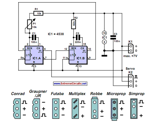
Individuals who frequently work with servos are likely familiar with situations where a servo tester is beneficial. The primary function of a servo tester is to produce a pulsing signal with a variable positive pulse width ranging from 1...

Utilize a PIC Microcontroller to Control a Hobby Servo. This guide outlines the process of incorporating hobby servos, typically found in remote-controlled airplanes, cars, and similar devices. To implement the control of a hobby servo using a PIC microcontroller, the...
The approximate center of the base was marked, and a hole was drilled large enough to accommodate a setscrew for the servo armature. The armature was then secured to the underside of the base using hot glue, ensuring that...
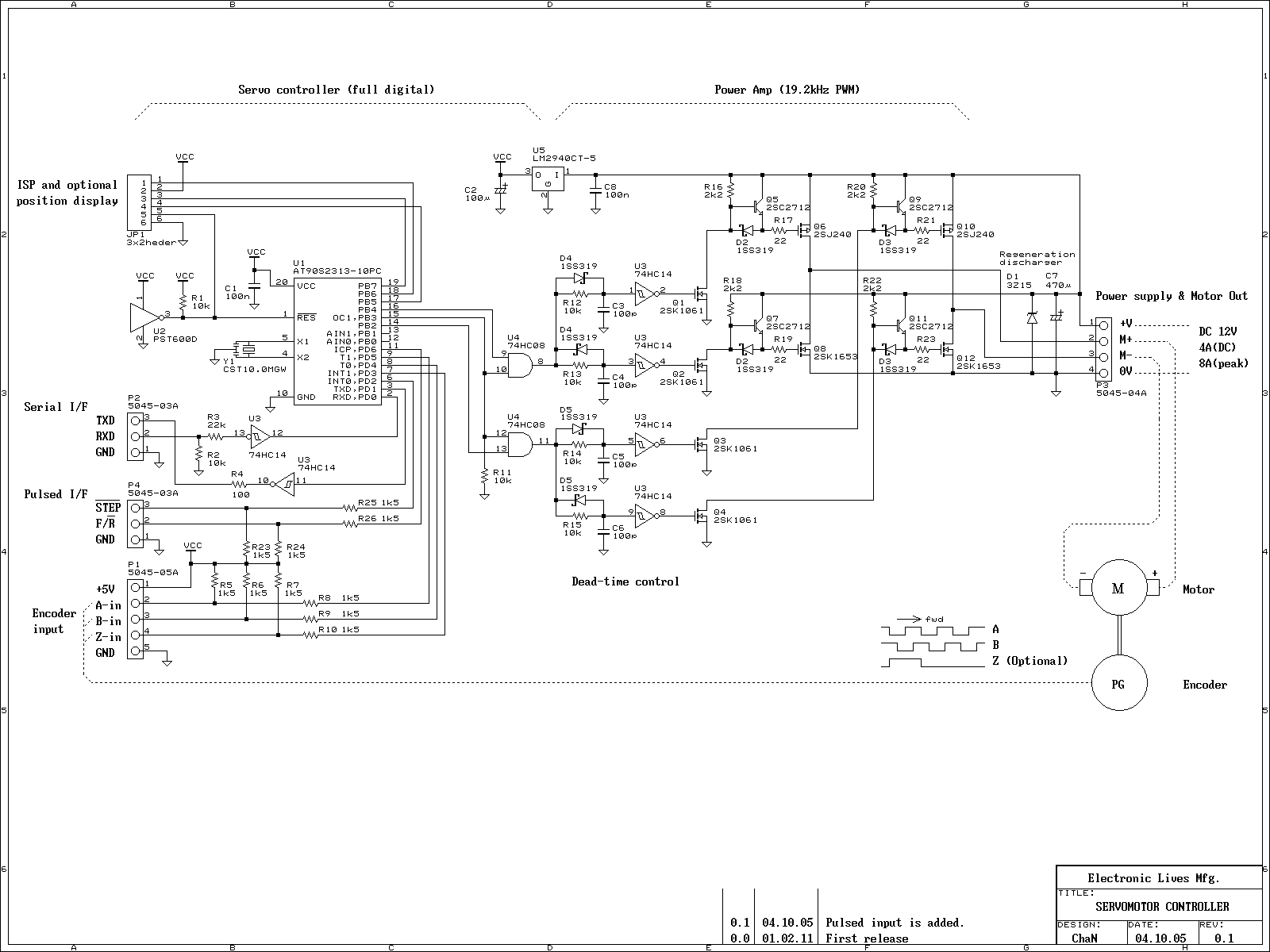
This is an experiment on the closed loop DC servomotor control system (SMC). It will be able to be used for practical use with/without some modifications. The closed loop servo mechanism requires real-time servo operations, such as position control,...
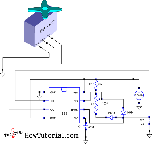
This document outlines the design of a simple circuit that enables control of a servo motor and allows for testing its functionality. The circuit for controlling a servo motor typically consists of a microcontroller, a power supply, and the servo...
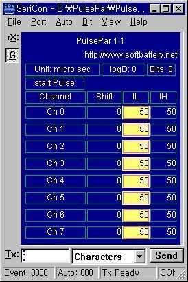
PulsePar turns a PC into a multi-channel pulse generator utilizing the parallel port. The period, duty and phase of each channel are adjustable so as to be used in PWM systems as well as in testing servo and stepper...