
rear wheel tachometer
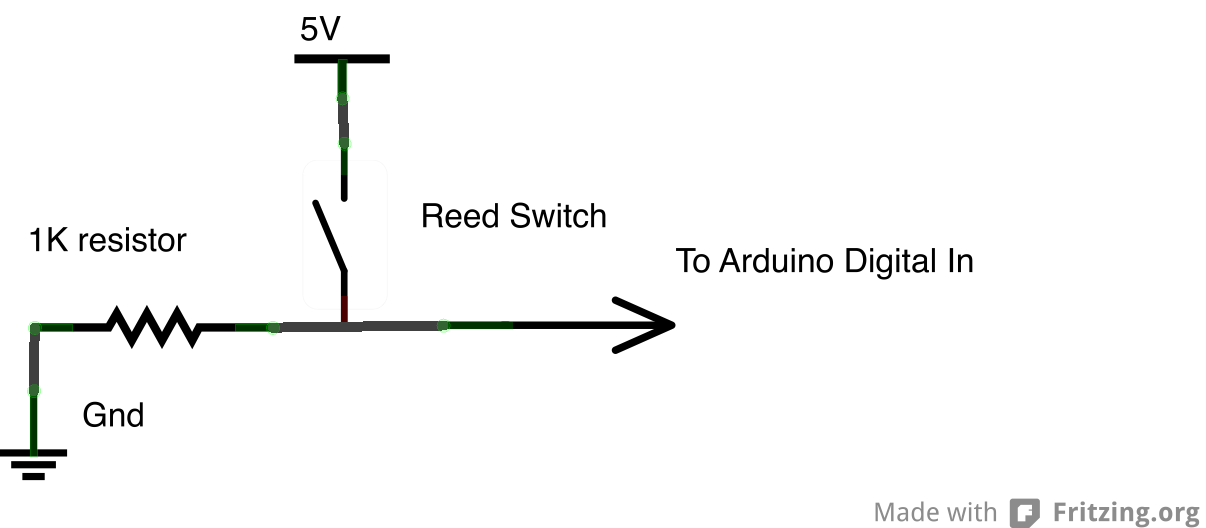
A comprehensive electronic schematic for the tachometer circuit can be designed to facilitate the measurement of the rear wheel's speed. The circuit will include a power source, typically a battery or the hub motor's output, to power the Arduino microcontroller. The Hall effect sensor will be connected to one of the digital input pins on the Arduino, allowing it to detect the magnetic field changes as the magnet attached to the wheel passes by. The output from the Hall effect sensor will be processed by the Arduino to count the revolutions and calculate the rotational speed in RPM.
The schematic will also include pull-up resistors connected to the Hall effect sensor to ensure stable readings by preventing floating pin states. Additionally, a capacitor may be included across the power supply pins of the Hall effect sensor for noise reduction, enhancing the reliability of the sensor's output. The Arduino will run a program that continuously monitors the sensor's state, incrementing a counter each time a transition from low to high is detected, indicative of a passing magnet.
To facilitate real-time feedback, an LCD display or serial monitor can be integrated into the circuit to visually present the calculated RPM. This display will be updated at regular intervals, providing participants with immediate information about the power generation from the bike's movement. The physical mounting of the sensor and magnet should be designed to ensure optimal alignment, minimizing the risk of miscounts due to misalignment or excessive distance.
Overall, this circuit design will enable effective monitoring of the rear wheel speed, contributing to the interactive experience sought by the Movable Party initiative.One of the goals of Movable Party is to provide an interactive experience for audiences/participants. Since power will be generated from a hub motor attached to the rear wheel of each bike (see this post ), the speed of the rear wheel directly translates to the amount of power generated.
Detecting how fast the rear wheel is moving thus seems likethe most obvious/important piece of data to capture from these stationary, power-generating bikes. The easiest way to detect the speed of the rear wheel (the way most bike computers work), is to make a tachometer simply put, a revolution counter. By counting the number of revolutions over a certain period of time, we can determine how fast the wheel is turning.
Basically, you want to count the number of times a specific spot on the wheel crosses a point of measurement, and divide by some time constant (e. g. Revolutions per Minute, RPMs). Electronically, you are triggering a switch every time this point on the wheel passes a fixed sensor.
Because the wheel is turning and the sensor is fixed, using a mechanical switch where there is contact every rotation will not work very well. For example, the mechanical switch will cause friction every rotation. Also, maintaining perfect distance between the wheel and the switch will be difficult. Instead, there are two common ways of detecting rotation that do not require contact between the sensor and the wheel optically and magnetically.
Due to my own personal familiarity with magnetic circuits, as well as the expense of using an optical system and concerns about the functionality of that system in ambient light, I have decided to pursue magnetic sensing. To construct a tachometer using a magnet, you attach the magnet to the wheel, and attach a sensor to the fork (at a fixed position).
As the magnet passes by the sensor, it triggers a switch that allows you to count the number of revolutions over a period of time. There are two types of sensors that accomplish this function: reed switches and Hall effect sensors. The reed switch is a simple switch that is closed (or opened) using a magnet. The Hall effect sensor converts changes in magnetic fields to analog voltage. The mystery of how the Hall effect actually works from a scientific standpoint goes beyond my level of understanding as a musician/tinkerer, but for our purposes the sensor functions like a digital switch.
(Fritzing, which I used to make the schematic below does not have a built-in part for a Hall Effect sensor, so I am using the mystery part) I tested both the reed switch (ORD-229-2530) and the Hall effect sensor (OH090U) with two types of magnets: 1/4 ³x1/16 ³ N42 neodymium magnet and 1/2 ³ x 3/16 ³ Ceramic Disc Magnet. I hooked both up to a simple sketch on the Arduino so I could see when the switches were open/closed.
Neither magnet worked very well with the reed switch unless I was basically touching the switch (conclusion: I would need stronger magnets). Both magnets worked with the Hall effect sensor. The neodymium magnet consistently triggered the switch 1/4 ³ from the sensor and the ceramic magnet worked 3/8 ³ from the sensor.
I am not sure what kind of sensing distance we will need for the rear wheel of the bike, however if these distances are too small, a stronger/larger magnet should work. My fellow Movable Partiers are working on getting their hands on some magnets from reclaimed bike computers, which hopefully will work well.
The goal of these preliminary tests was to make sure I could actually build the circuit and get it to work. The next step is to hook it up to a bicycle and make sure we can get an accurate count of rotations. The physical connection to the bicycle represents one challenge that should be figured out sooner rather than later.
For the electronics, we will probably need to implement some kind of edge detection code on the Arduino to make sure that we only get one trigger every time the 🔗 External reference
Related Circuits
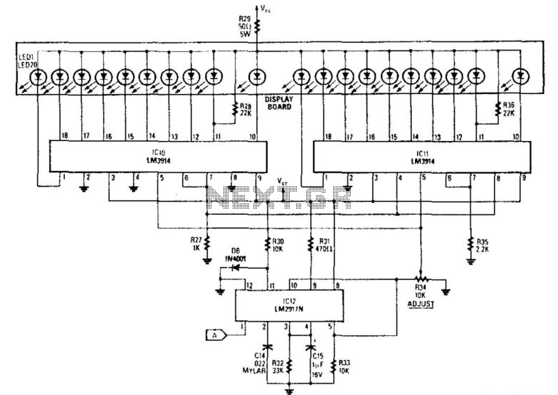
The analog display consists of a frequency/voltage converter (IC12) and bar-graph segment drivers IC10 and IC11. More: R34 is the calibration adjustment and is set so that an engine rpm of 5 000 to 7000 rpm lights the first...
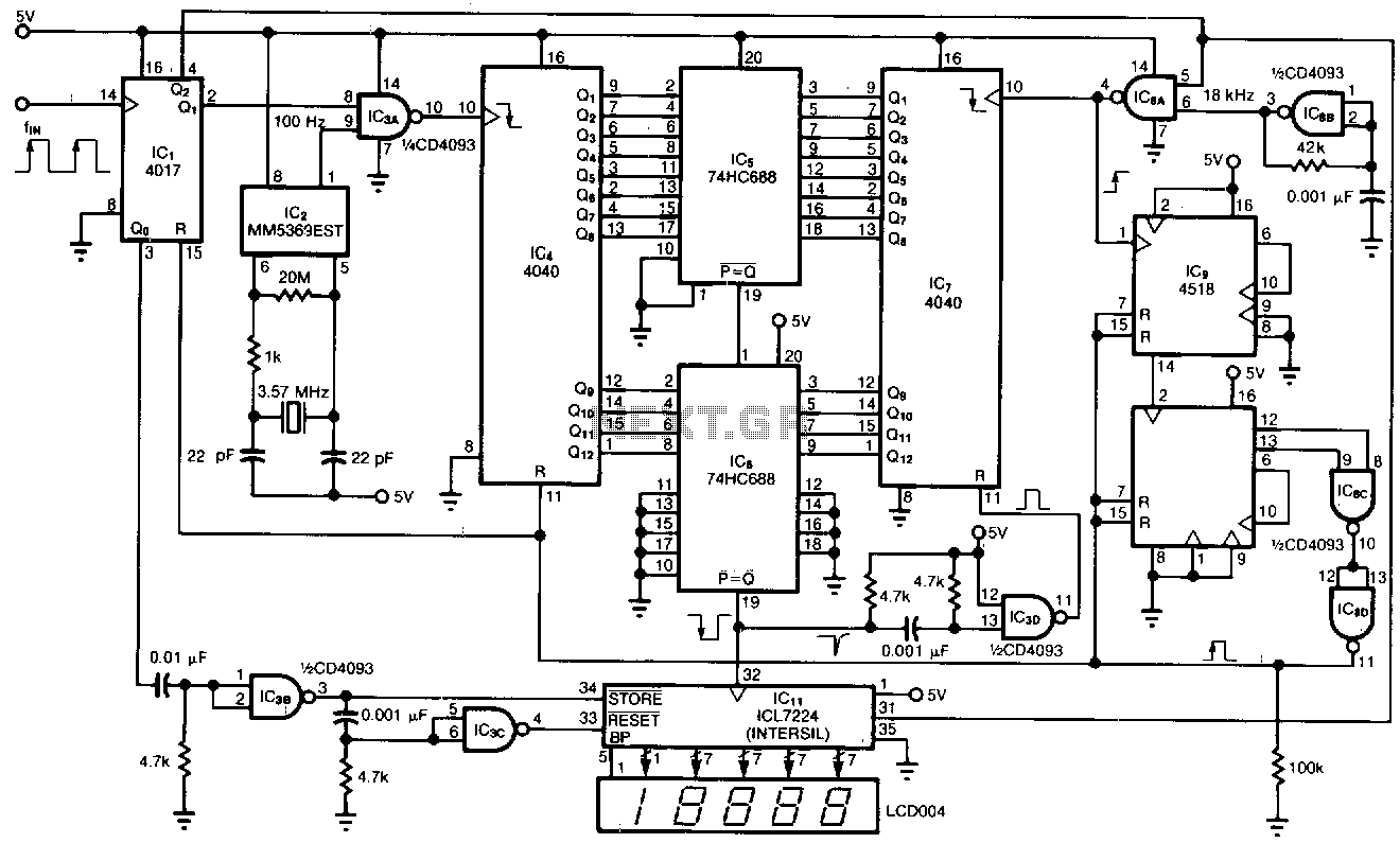
This tachometer allows for the measurement of heartbeats, respiratory rates, and other low-frequency events that occur at intervals ranging from 0.33 to 40.96 seconds. The circuit detects the frequency, calculates the corresponding pulses per minute, and updates the LCD...
This project allows for the control of two wheels or tracks from a PC serial port without any wired connections. The system operates at 2400 baud. A Basic Stamp microcontroller is utilized, with the Basic Stamp I being used...
This digital DIY tachometer for bicycles utilizes two reed switches to gather speed information. The reed switches are positioned near the wheel rim, where permanent magnets, attached to the wheel spokes, pass by and activate the switches. The speed...
This article discusses the design of an LED driver for automotive rear lights. It demonstrates that dimming is most effectively accomplished using pulse-width modulation (PWM) in conjunction with an LED driver integrated circuit (IC) that removes the requirement for...

The circuit for the Digital Tachometer/RPM Counter consists of a few components. They should be connected according to the provided circuit diagram. The PIC used is on a demonstration board, meaning the clock, power, and ground pins are already...
Warning: include(partials/cookie-banner.php): Failed to open stream: Permission denied in /var/www/html/nextgr/view-circuit.php on line 713
Warning: include(): Failed opening 'partials/cookie-banner.php' for inclusion (include_path='.:/usr/share/php') in /var/www/html/nextgr/view-circuit.php on line 713