
Digital Bike Tachometer Circuit Schematic Diagram
This digital tachometer circuit is designed to provide accurate speed readings for bicycles by employing a straightforward yet effective method of pulse counting. The reed switches, which act as sensors, are strategically placed to maximize their interaction with the permanent magnets affixed to the spokes of the wheel. Each time a magnet passes the reed switch, it closes the circuit, generating a pulse that is sent to the counting circuitry.
The use of two 4026 ICs is integral to the operation of the tachometer. These ICs are responsible for counting the incoming pulses and translating this count into a readable format for the 7-segment LED displays. The 4026 ICs can handle the decoding of the binary count, allowing for a clear and easy-to-read output that reflects the speed of the bicycle in real-time.
To ensure reliability in pulse detection, RS flip-flops (U3 and U4) are implemented as anti-bounce mechanisms. This is crucial because mechanical switches can produce false signals due to contact bounce, which may lead to inaccurate speed readings. By utilizing flip-flops, the circuit can filter out these unwanted signals, providing a more stable input to the counting ICs.
The measuring period, determined by the monostable multivibrator (U5/U6), is adjustable through a potentiometer (P1). This feature allows users to calibrate the tachometer according to their specific needs or to match readings with a known accurate tachometer. The calibration process involves adjusting the timing to ensure that the displayed speed is consistent with actual speed measurements.
The reset function provided by the circuit (U1/U2) allows the user to clear the counts when necessary, ensuring that the tachometer can be reset for new measurements. The design acknowledges the limitations of battery operation, opting for an activation mechanism that conserves power by only turning on when a button is pressed, rather than maintaining continuous operation.
For optimal performance, it is recommended to install at least three permanent magnets on the wheel. This configuration ensures that the reed switches receive a sufficient number of pulses to yield accurate speed readings, especially at lower speeds. The calibration process can be facilitated by comparing the readings from this DIY tachometer with those from a commercially available calibrated tachometer, allowing for fine-tuning of the system for precise measurements.This digital DIY tachometer for bikes uses two reed switches to get the speed information of the bicycle. The reed switches are installed near the rim of the wheel where permanent magnets pass by. The permanent magnets are attached to the wheelspokes and activate the reed switches everytime they pass by it.
The speed is digitally displayed. The ta chometer circuit works according to this principle; the pulses created by the reed contacts are counted within a certain time interval. The resulting count is then displayed and represents the speed of the bike. Two 4026 ICs are used to count the pulses, decode the counter and control two 7-segment LED display. RS flip-flops U3 and U4 function as anti-bounce. The pulses arrive at the counter`s input through gate U7. The measuring period is determined by monostable multivibrator U5/U6 and can be adjusted through potentiometer P1 so that the tacho can be calibrated.
The circuit U1/U2 resets the counters. Since batteries are used to power the circuit, it is not practical to support the continous display of speed information. This circuit is not continously active. The circuit is activated only after a button is pressed. At least three permanent magnets must be installed on the wheel. The circuit can be calibrated with the help of another precalibrated tachometer. You are reading the Circuits of Digital Bike Tachometer Circuit And this circuit permalink url it is 🔗 External reference
Related Circuits
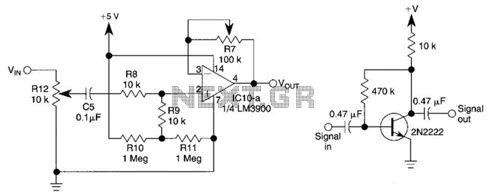
This circuit utilizes one-quarter of an LM3900 to create a simple variable-gain front end for an oscilloscope. R7 serves as the gain control. Additionally, a basic preamplifier is included for applications requiring more than 10X gain. The circuit employs the...
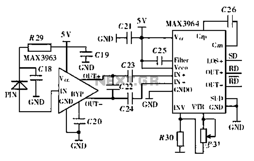
Ethernet is the most widely used networking technology, known for its high reliability, informative media, and ease of expansion and updates. It is commonly utilized in businesses, schools, and various other fields. According to the IEEE802.3 Ethernet specification, the...
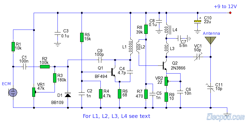
The ZN414 is an economical, single-chip AM radio integrated circuit introduced in 1972 by Ferranti. The TDA7000 is a monolithic integrated circuit designed for mono FM portable radios or receivers, focusing on minimizing size. Additionally, there is an FM...
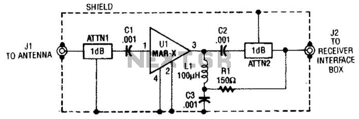
The MAR-x preamplifier is designed to operate within a frequency range of up to 1.5 or 2 GHz, depending on the selected MAR-x integrated circuit (IC). For applications requiring a low noise figure, ATTN1 should be omitted. Both ATTN1...
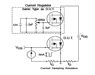
The IRF9540N Gate Charge Test Circuit is illustrated in the diagram below. The IRF9540N is recognized as a rectifier device that employs advanced processing techniques to attain an exceptionally low on-resistance per unit area, as stated in the datasheet....
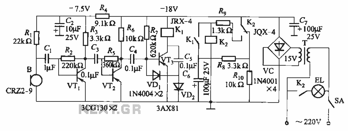
The circuit utilizes relay control. The voice switch operates as follows: upon the first clap, the load (lights) is activated; upon the second clap, the load (lights) is deactivated. This system can be employed to control lighting in residential...