
Receiver Af Noise Limiter For Low-Level Signals Circuit

The audio preamplifier circuit is designed to enhance weak audio signals, typically ranging from 10 mV to 1 V, ensuring that these signals can be processed effectively by subsequent stages, such as a diode clipper. The primary function of the preamplifier is to increase the amplitude of the input signal while maintaining signal integrity and minimizing noise.
The circuit typically consists of a transistor or operational amplifier configured in a non-inverting amplifier configuration, providing a high input impedance to avoid loading the signal source. This high input impedance is crucial for preserving the quality of the audio signal, especially when dealing with sensitive sources like microphones or low-level audio outputs.
The gain of the preamplifier can be adjusted through feedback resistors, allowing for flexibility in accommodating various input levels. Capacitors may be used for coupling and decoupling to block DC offsets while allowing AC audio signals to pass through. Additionally, the power supply for the preamplifier must be sufficiently stable to prevent fluctuations that could introduce noise into the amplified signal.
Following amplification, the signal is fed into a diode clipper, which serves to limit the amplitude of the signal to prevent distortion that can occur when the signal exceeds a certain threshold. The diode clipper circuit typically consists of diodes arranged in a configuration that allows for clipping of both the positive and negative peaks of the audio waveform, thus shaping the output signal for further processing or amplification.
Overall, this combination of a preamplifier and diode clipper is essential in audio processing applications where signal integrity and control of signal levels are paramount, ensuring the final output remains within acceptable limits for subsequent stages in the audio chain. A preamplifier in the audio frequency range amplifies a noisy audio signal to drive a diode clipper. Suitable audio input levels would be in the 10-mV to 1-V range.
Related Circuits
The schematic is in PDF format and cannot be sent through this site. It is recommended to check a specific website that contains various schematics, including older posts that might have the schematic needed. A WS-55807 model is experiencing...

This design circuit for audio amplifiers with DC coupling to the load is not commonly used today, despite its clear advantages. One advantage is the elimination of the need for a second (symmetric) power supply, and another is the...
Two working examples have been assembled, one utilizing a PNP and an NPN transistor, and the other employing two MOSFETs. Both circuits function correctly, but as anticipated, the MOSFET circuit draws significantly less current (0.1 mA compared to 4.5...
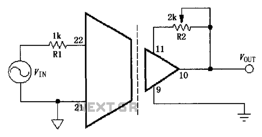
The gain adjustment circuit for the ISO103 is illustrated. The circuit features a gain trimming potentiometer, R2, which serves to enhance the gain accuracy and offset of the ISO103, thereby allowing for external adjustments. R2 provides a gain trim...
This is a simple flyback tester circuit designed to test high-frequency transformers, such as those used in switch-mode power supplies (SMPS) or flyback transformers. The circuit operates as an astable multivibrator with a frequency of approximately 90 kHz, powered...
When a network needs to transfer small blocks of information over long distances, RS-485 is often the preferred interface. Network nodes can include PCs, microcontrollers, or any devices capable of asynchronous serial communications. Compared to Ethernet and other network...