
ISO103 gain adjustment circuit diagram

The ISO103 gain adjustment circuit is designed to optimize the performance of the ISO103 instrumentation amplifier by enabling precise control over gain settings. The primary component, R2, acts as a variable resistor, allowing users to fine-tune the gain to meet specific application requirements. The nominal gain trim provided by R2 is 0.5%, which is critical for applications demanding high accuracy in signal amplification.
In scenarios where enhanced fine-tuning is essential, the circuit can be modified by increasing the resistance values of R1 and R2 to 2kΩ. This adjustment introduces an additional 1% fine adjustment range, which is particularly beneficial in precision measurement applications. However, it is important to note that this configuration imposes a specific design constraint: R2 must be set to twice the resistance value of R1 (i.e., R2 = 2R1).
This relationship between R1 and R2 is crucial for maintaining the integrity of the gain adjustment. The careful selection of these resistor values ensures that the overall gain of the ISO103 remains within desired specifications while providing the necessary flexibility for fine-tuning. The implementation of this gain adjustment circuit can significantly enhance the performance of the ISO103 in various electronic applications, particularly in environments where signal integrity and accuracy are paramount. As shown for the gain adjustment circuit ISO103. Circuit gain trimming potentiometer R2 (general ISO103 gain accuracy and offset the need for external adjustment), R2 provides 0.5% gain trim. As the need for greater fine-tuning range can be increased R1, R2 the resistance of each resistor R1 increases 2k, an additional 1% of the fine adjustment range, but requires R2 2R1.
Related Circuits
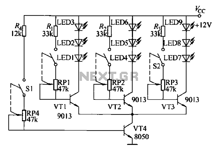
The circuit is designed to facilitate the teaching of color synthesis principles in color television, allowing students to better understand the concept through visual aids. It effectively reproduces color signals, thus simplifying the abstract nature of color synthesis. The...
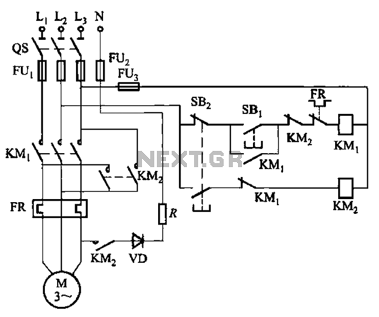
The circuit shown in Figure 3-139 utilizes a rectifier diode brake for neutral grounding in a three-phase, four-wire power supply system. The circuit employs a rectifier diode configuration to achieve effective neutral grounding, which is crucial for maintaining system stability...
1996 Isuzu Rodeo Headlight Wiring Diagram. The 1996 Isuzu Rodeo headlight wiring diagram provides a detailed representation of the electrical connections and components involved in the vehicle's headlight system. This diagram is essential for understanding how the headlight assembly operates...
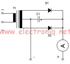
This simple lead-acid battery charger requires a center-tapped transformer (12V 0V 12V) capable of delivering a current of 5 amperes, two diodes, and one capacitor. To charge the batteries, the positive and negative terminals from the charger must be...
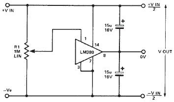
A simple split power supply circuit can be designed using the schematic diagram based on the LM380 audio power integrated circuit (IC). The output voltage regulation is dependent on the circuit feeding the LM380. The power dissipation is approximately...
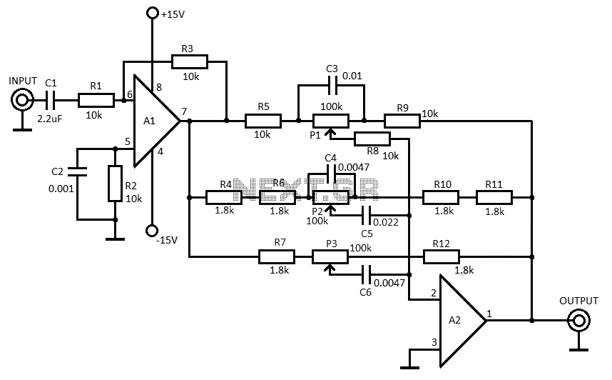
This 3-band equalizer circuit is an active filter network designed to adjust bass, midrange, and treble audio frequencies. It utilizes the LM833 operational amplifier from National Semiconductors, which is known for its very low noise figure and wide frequency...