
Pressure Sensor Signal Conditioning Circuit with Single Op-Amp

The pressure sensor signal conditioning circuit is designed to convert the raw output signal from a pressure sensor into a more usable form for further processing or display. The circuit typically includes components such as operational amplifiers, resistors, capacitors, and sometimes analog-to-digital converters (ADCs) to enhance the signal quality and ensure accurate readings.
In a basic configuration, the pressure sensor generates a voltage output that corresponds to the applied pressure. This output may be weak and susceptible to noise, necessitating signal conditioning. An operational amplifier (op-amp) can be employed to amplify the sensor's output signal. The gain of the op-amp can be adjusted using feedback resistors, allowing for calibration to the specific range of pressure measurements required.
Filtering may also be incorporated into the circuit to eliminate high-frequency noise. This can be achieved using passive RC (resistor-capacitor) filters or active filters that utilize additional op-amps. The choice of filtering method depends on the specific application and the frequency characteristics of the noise present in the environment.
For applications that require digital processing, the conditioned analog signal can be fed into an ADC. The ADC converts the analog voltage into a digital signal, which can then be processed by microcontrollers or digital signal processors (DSPs) for further analysis, display, or control purposes.
Overall, the pressure sensor signal conditioning circuit plays a crucial role in ensuring accurate and reliable pressure measurements by improving the signal quality and making it suitable for subsequent electronic processing.This is pressure sensor signal conditioning circuit. It is simple and inexpensive circuit because it has small geometry and simple pressure sensor. It just uses. 🔗 External reference
Related Circuits

As shown in FIG XTR108, a four-wire RTD is connected to the circuit. In practical applications, the lead resistance of a four-wire RTD is typically not equal, which necessitates the use of a precision operational amplifier, OPA277, to minimize...
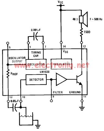
The LM1830 low-level detector can utilize an audio indication (speaker) or a visual indicator (LED - light-emitting diode) that activates when the level is too low. This low-level detector circuit generates a 500 Hz audio signal when the level...
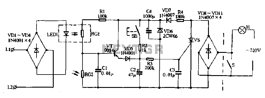
Diodes VD8 to VDI1 function as part of the main circuit isolation, with SCR serving as a composition control switch. The buck regulator circuit is composed of a stable orbital tube VD6 and a simple resistor-capacitor combination (C4). The...

The transmitter is constructed on a Printed Circuit Board (PCB). This board incorporates track inductors for L1, L2, and part of L3. The section surrounding Q1 functions as the oscillator section, with the oscillation frequency determined by L1, C4,...
The circuit involves a switch (S1) that facilitates the release of current when it reaches the shut-off mechanism. The circuit operates by utilizing a switch (S1) that plays a crucial role in controlling the flow of current within the system....
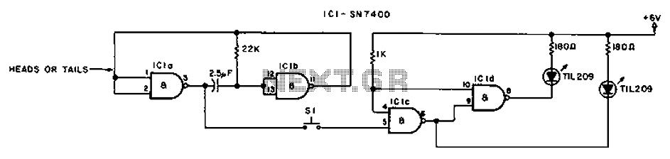
A diode, such as the IN4148, has a typical temperature coefficient of -2 mV/°C at a 1 mA diode current. Transistors Q1 and Q2 form a constant current source. Diode D1 serves as the temperature sensor. Integrated circuits ICl-a...