
rfid How to design an Oscillator Circuit (500 MHz range) with no Op amps
 with no Op amps")
The oscillator circuit for RFID applications requires careful consideration of various design parameters to ensure it functions effectively at high frequencies. A class E oscillator is a popular choice for generating high-frequency signals due to its efficiency and simplicity, but it necessitates precise component selection and configuration.
To create a reliable 500 MHz sine wave, the following components and considerations are essential:
1. **Transistor Selection**: A high-frequency transistor, such as a FET or a BJT rated for RF applications, should be chosen. The transistor must support the necessary frequency and provide sufficient gain.
2. **Resonant Tank Circuit**: The core of the oscillator is the resonant tank circuit, typically consisting of an inductor (L) and a capacitor (C). The values of these components must be calculated to resonate at the desired frequency. The resonant frequency \( f \) can be calculated using the formula:
\[
f = \frac{1}{2\pi\sqrt{LC}}
\]
Proper tuning of L and C is crucial to achieving the target frequency.
3. **Feedback Network**: A feedback network is required to sustain oscillation. This can be achieved through a combination of resistors and capacitors that ensure the correct phase shift and gain for oscillation.
4. **Power Supply**: The circuit must have a stable power supply to maintain consistent operation. Voltage regulation may be necessary to avoid fluctuations that could affect the output frequency.
5. **Output Filtering**: To obtain a clean sine wave, output filtering may be implemented. This can involve additional LC filters that remove harmonic content and ensure the output is suitable for RFID applications.
6. **PCB Design**: At high frequencies, the layout of the printed circuit board (PCB) becomes critical. Short traces, proper grounding, and minimized parasitic capacitance and inductance are essential to maintain signal integrity.
7. **Testing and Tuning**: After assembly, the circuit should be tested with an oscilloscope to verify the output waveform. Adjustments may be necessary to fine-tune the component values and ensure the oscillator operates at the desired frequency with minimal distortion.
By addressing these components and considerations, a functional class E oscillator capable of generating a 500 MHz sine wave for RFID applications can be successfully designed and implemented.An Oscillator circuit which can produce a good sine wave with a frequency of at least 500 Mhz. This is for RFID applications. I have tried to use an class E oscillator, but i cant seem to get the design right. Can anyone help me out 🔗 External reference
Related Circuits
Many TOPSwitch TOP223 flyback power supply applications require two or more outputs to supply a variety of secondary circuits. Typical consumer applications of these multiple output converters include televisions and related products such as set-top decoders and video cassette...

The schematic for the board is illustrated below. The three primary components of the board include (1) the power input and voltage regulation, (2) the L297 input and outputs, and (3) the L298 stepper motor control circuit. The motor...
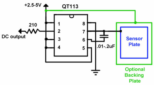
The QT113 is a capacitance touch sensor that does not require AC line voltage to operate. Instead, it detects changes in capacitance caused by the proximity of a user’s body. A sensor plate measuring 2 inches square can sense...
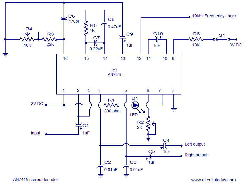
AN7415 based FM stereo demodulator circuit. 1.6 to 7V operating voltage range. High gain and low distortion. The AN7415 is a versatile integrated circuit designed for FM stereo demodulation applications. This circuit operates within a voltage range of 1.6 to...
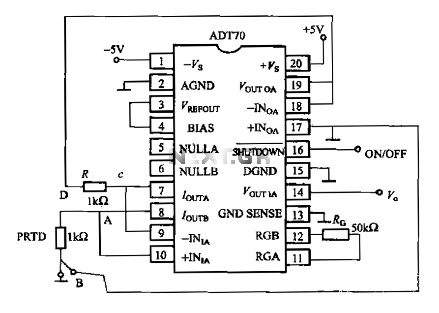
The AD170 basic electrical parameters include a temperature coefficient of 25 ppm/°C and a temperature measurement accuracy of ±1°C, with a maximum temperature range of -200°C to +100°C. The power supply required is +5V or -5V, and the operating...
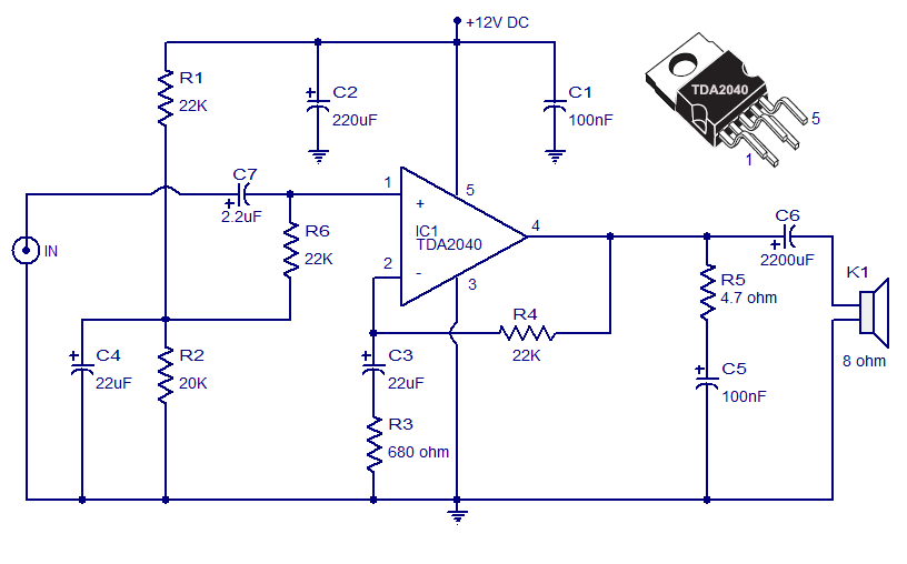
The Car Stereo Amplifier Circuit featuring the TDA2040 is presented here. The TDA2040 is a monolithic integrated audio amplifier that operates in Class AB mode. This integrated circuit includes built-in short circuit protection and thermal management features, allowing it...