
Siren circuit

The circuit described is designed to generate an altered sound resembling that of a siren. It utilizes an oscillator formed by two NAND gates (IC1a and IC1b), which operate at a very low frequency. This low-frequency oscillation is critical as it drives an electronic switch (IC2), which can open and close in sync with the oscillation frequency.
When the switch IC2 is closed, the supply voltage charges capacitor C3 through resistor R2. The charging of C3 is essential as it stores energy that will be released when the switch opens. When IC2 opens, capacitor C3 discharges through resistor R3. The voltage across C3, which varies with the charge and discharge cycle, is used to control the Voltage Controlled Oscillator (VCO) within the Phase-Locked Loop (PLL) IC3. The output from the VCO produces the altered sound characteristic of a siren.
The circuit allows for experimentation with the values of the resistors and capacitors to modify the sound produced. Specifically, resistor R1 and capacitor C1 are used to control the timing of the operation, influencing how long the circuit remains in each state of oscillation. Resistor R4 and capacitor C2 are responsible for determining the frequency of the sound produced, while resistor R3 and capacitor C3 affect the characteristics of the sound change. By adjusting these components, various siren-like sounds can be achieved, making the circuit versatile for different applications.With this circuit we can create a altered sound of siren. The oscillator IC1a-b is constituted by two gates NAND, oscillating in very low frequency. This oscillation drive the IC2, that is a electronic switch, which opens and closes in the rythm of oscillation. When closes the switch then the voltage of supply charge the capacitor C3 through the resistance R2. When switch IC2 opens, the C3 discharge through the R3. The voltage with which is charge the C3, regulates the VCO of IC3, that is PLL, so that we have in the exit his one altered sound.
You can experiment with the prices of resistances and capacitors in order to you change the sound of siren. The R1, C1 check the time of operation, the R4, C2 check the frequency of produced sound and the R3, C3 check the change of sound.
🔗 External reference
Related Circuits
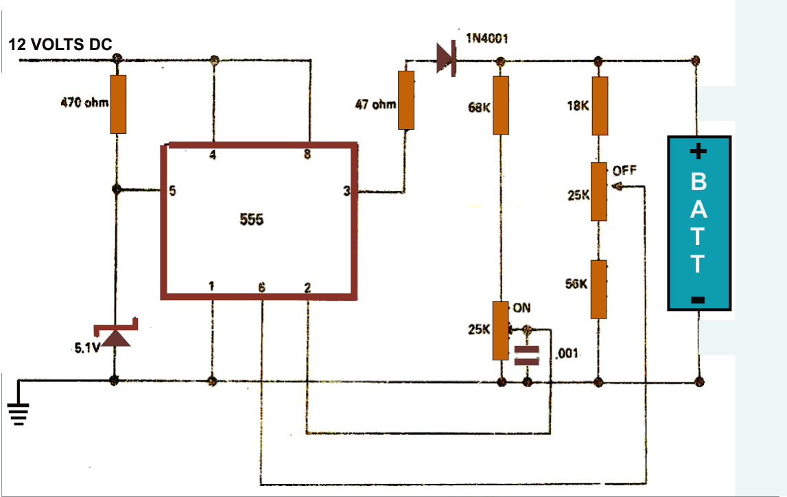
The simple battery charger circuit design presented here utilizes the versatile IC 555 as its primary component. This circuit is capable of charging various types of rechargeable batteries within the specified limits outlined in the article. The battery charger circuit...
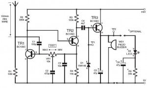
This do-it-yourself lightning detector circuit is a highly sensitive continuous electricity detector that can provide an early warning of approaching storms from inter-cloud discharges prior to an earth-to-sky lightning strike occurring. An aerial antenna made of a short length...
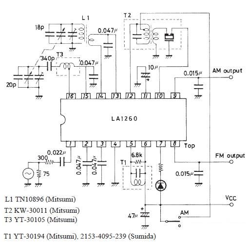
A very simple FM IF MW radio receiver circuit can be designed using the LA1260 IC manufactured by Sanyo Semiconductor. This FM IF MW radio receiver circuit schematic shows that the LA1260 IC can be utilized in AM and...
Electrical lines that include lighting circuits originate from the main distribution panel of the installation. Each line consists of three conductors: phase, neutral, and ground. All three conductors extend to the terminal point of each luminaire, and if the...
This circuit generates dual-tone bell ringing similar to most doorbell units. It can be used in various applications beyond just doorbells. Several options will be provided in the notes to accommodate different needs. The circuit, as depicted in the...
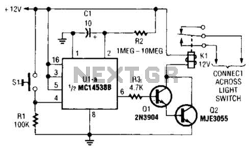
A normally open pushbutton switch (SI) provides a positive input pulse to pin 4 of U1, activating the integrated circuit (IC). The output from U1 at pin 6 delivers base-drive current to a Darlington pair consisting of Q1 and...