
Recovery Node

The recovery node serves as a critical component in the LV2 system, ensuring that the parachute deployment process is executed safely and reliably during descent. The choice of using pyrotechnic actuators and electric matches is driven by the need for precise and immediate deployment of the parachutes, which is essential for achieving a controlled descent. The use of a microcontroller in the CORE section allows for sophisticated control and monitoring capabilities, enabling the system to react quickly to changing conditions during descent.
The HAP section is particularly important for maintaining power availability, as it provides redundancy through the integration of a rechargeable lithium battery. This feature ensures that even in the event of a power failure, the recovery system can continue to function, thus enhancing reliability.
The DTMF section adds an additional layer of functionality by allowing for remote monitoring and control through audio signals, which can be crucial for telemetry and data collection during the recovery phase.
Finally, the PYRO section's design emphasizes safety and reliability, incorporating multiple layers of protection against accidental activation and ensuring that the high-voltage components are well-managed. The use of voltage triplers and capacitive discharge supplies reflects a careful consideration of the electrical requirements necessary to safely ignite the parachute deployment mechanisms.
Overall, the recovery node's design is a testament to the balance between innovation, safety, and reliability, reflecting the rigorous engineering principles that guide the development of aerospace systems.The "recovery node" is the pyrotechnic controller board designed for LV2. LV2 uses two different parachutes during its descent. The drogue chute opens first. The drouge is a small parachute that stabilizes the rocket but allows it to fall at a fairly high speed in order to minimize the distance the rocket drifts with the wind during descent. For r ecovery it is desirable that the rocket land close to the launch point. The descent rate on the drouge chute is too fast for a damage-free landing, so about 500 meters above ground level the drogue chute pulls out the larger main parachute. The deployment of the parachutes is achieved by pyrotechnic actuators. which are in turn initiated by "Electric Matches". (On LV2 these are Oxral electric matches. ) The electric match heads are about the same size as those of ordinary kitchen matches and burn with only slightly more vigor.
Their electrical firing energy threshold is about 2mJ. The two towering goals of the recovery system are reliability and safety. Parachute failure probably means complete destruction of our vehicle. At least as significantly, the pyrotechnic actuators are potentially dangerous to our people. To minimize the danger to people we have firstly designed to minimize the inherent danger in the actuators themselves. Secondly we always handle the devices in such a way as to avoid injury should an accidental activation occur.
Our third line of defense involves a system of interlocks in the recovery node. Reliability is attained by good design. This means good overall design practice, and also minimizing the number of critical components, thorough testing, and some redundancy for low reliability components. These desirable properties are constrained by the typical PSAS projects goals which seek to minimize the complexity, price, time, weight and size of each component.
Each of these specifications descend directly from LV1 hardware but in LV2 each has a slightly different twist. Because it is interesting to understand the reasoning that drives a design, a little history is offered here.
Referring to the block diagram, the circuit is divided into sections, namely the CORE, HAP, DTMF and PYRO sections. The CORE section contains the CAN bus interface which includes the main 14V DC power bus as well as the two wire CAN communications interface.
The CORE section has a PIC18F458 microprocessor and a 1. 54MHz switching power supply [SPS] to convert the main bus power down to 5 Volts. The intention is to re-use the CORE section for all new LV2 CAN nodes. To the right of the CORE section is the HAP which stands for High Availability Power supply. The HAP contains another 1. 54MHz switching power supply operating in boost mode. This supply provides a 5V output using either the CORE SPS voltage or a single cell rechargeable lithium battery as input. The HAP automatically switches to battery power when the SPS power fails. In the battery backup [BB] section of the HAP there are charging, monitoring and over voltage protection circuits for the lithium battery At the lower left of the diagram is the DTMF section.
This is basically a single chip DTMF-tone to 4-bit-parallel I/O decoder. The DTMF section connects to the 2 meter [2m] radio board which provides an analog audio signal. PYRO is the recovery node`s final section. It contains four 100V igniter switches powered from a common capacitive discharge supply. The 100V [HV] supply is generated using yet another 1. 54MHz switching power supply boosting 5V to about 33V which is then run through a voltage tripler into the discharge capacitor. There is a separate voltage tripler to provide the required 12V power supply for the high side switch drivers.
For testing there is a disconnectable voltage divider that may be used to measure the HV voltage, or if left connected serves as a bleeder resistor to speed up discharging of the high voltage supply. Lastly there is an externally 🔗 External reference
Related Circuits
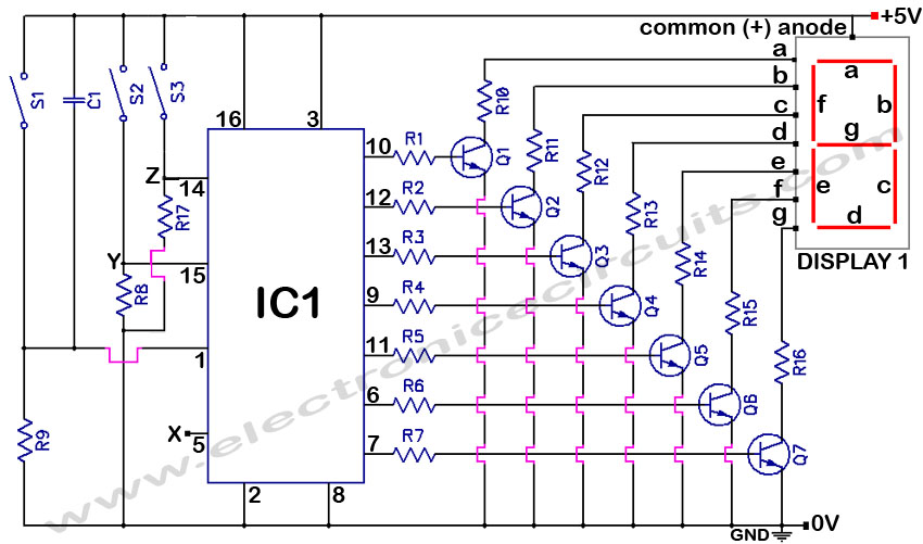
4033 7 Segment Common Anode Display Event Counter Circuit. This circuit can count from 0 to 9 with a reset function and a display test feature. The 4033 7-segment common anode display event counter circuit is designed to count events...
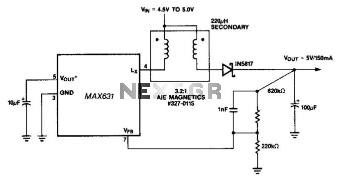
This circuit offers a distinctive solution to a prevalent power distribution issue at the system level. When the supply voltage to a remote board must travel through a lengthy cable, the voltage at the termination point may decrease to...
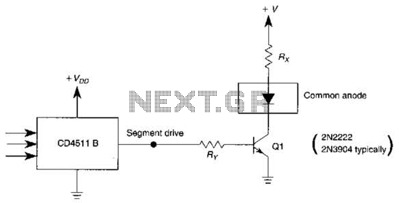
The use of a switching transistor, such as a 2N2222 or 2N3904, enables the operation of the CD4511B with a common-anode display. The transistor should be selected to provide approximately 1 mA to drive Q1, while resistor Rr must...
This is a High Voltage switching device for driving coils and which have big impedance when it is switched off. It can be used in Back-EMF energy recovery tests, Newman coils electronic commutator. This device is driven by an...
A clock-and-data recovery (CDR) circuit is utilized to recover the clock from a transmitted data stream and re-time that data with the recovered clock. These circuits are generally positioned at the front-end of receiver chips to extract the clock...
This is the unedited version of the article "Improved Anode-Circuit Parasitic-Suppression For Modern Amplifier-Tubes," which was published on page 36 of the October 1988 issue of QST. A subsequent discussion on this topic appeared in the September and October...